Tracking Control Apparatus And Method, And Signal Processing Apparatus

a control apparatus and signal processing technology, applied in the direction of data recording, instruments, disposition/mounting of heads, etc., can solve the problems of low gain of control loops and unstable, and achieve the effect of improving the precision of tracking control or focus control

Inactive Publication Date: 2007-09-20
PANASONIC CORP
View PDF0 Cites 1 Cited by
  • Summary
  • Abstract
  • Description
  • Claims
  • Application Information

AI Technical Summary

Benefits of technology

[0024] A tracking control method according to the present invention is a tracking control method performing tracking control by using a tracking control apparatus included in an optical disc apparatus for performing reproduction for an optical disc capable of reproduction-only and performing recording / reproduction for an optical disc capable of recording / reproduction, wherein the tracking control apparatus includes: focusing means for forming an optical beam spot on a recording surface of an optical disc by focusing light beam on the recording surface of the optical disc, moving means for moving the optical beam spot in a radial direction of the recording surface of the optical disc; and photodetection means having a light receiving surface for detecting light reflected off the optical disc, in which the light receiving surface is separated into a plurality of areas, and each of the plurality of areas is formed to generate a received light quantity signal in accordance with a received light quantity and to output the received light quantity signal, the tracking control method comprising the steps of: using a filter section including a plurality of low-pass filters to remove a component having a frequency equal to or higher than a predetermined cutoff frequency from each of a plurality of the received light quantity signals output from the photodetection means; generating a tracking error signal indicating an amount of deviation of the optical beam spot from a track to be scanned on the recording surface of the optical disc by performing a predetermined calculation with respect to a plurality of signals output from the photodetection means when an optical disc inserted into the optical disc apparatus is the optical disc capable of reproduction-only; generating a tracking error signal indicating an amount of deviation of the optical beam spot from a track to be scanned on the recording surface of the optical disc by performing a predetermined calculation with respect to a plurality of signals output from the filter section when an optical disc inserted into the optical disc apparatus is the optical disc capable of recording / reproduct ion; and driving the moving means such that the optical beam spot follows the track on the recording surface of the optical disc in accordance with the tracking error signal, thereby achieving the above-describe object.
[0026] The optical disc apparatus according to the present invention includes a filter section removing high-frequency band components immediately after a received detection section, the filter is operated for a disc capable of recording / reproduction which does not require high-frequency band components when generating a tracking error signal, and the filter is not operated for a disc capable of reproduction-only which requires high-frequency band components. Thus, unnecessary components due to modulation components of laser power (recording power) can be removed, while remaining components of the tracking error signal necessary for the tracking control. As a result, a precision of the tracking control or the focus control can be improved.

Problems solved by technology

This is because it was found that the above-mentioned high-frequency component saturate the operational circuits, and the amplitude of the tracking error control which passes through the antialiasing filter becomes small, causing a control loop gain to be lowered and unstable.

Method used


Image

  • Tracking Control Apparatus And Method, And Signal Processing Apparatus
  • Tracking Control Apparatus And Method, And Signal Processing Apparatus
  • Tracking Control Apparatus And Method, And Signal Processing Apparatus

Examples


embodiment 1

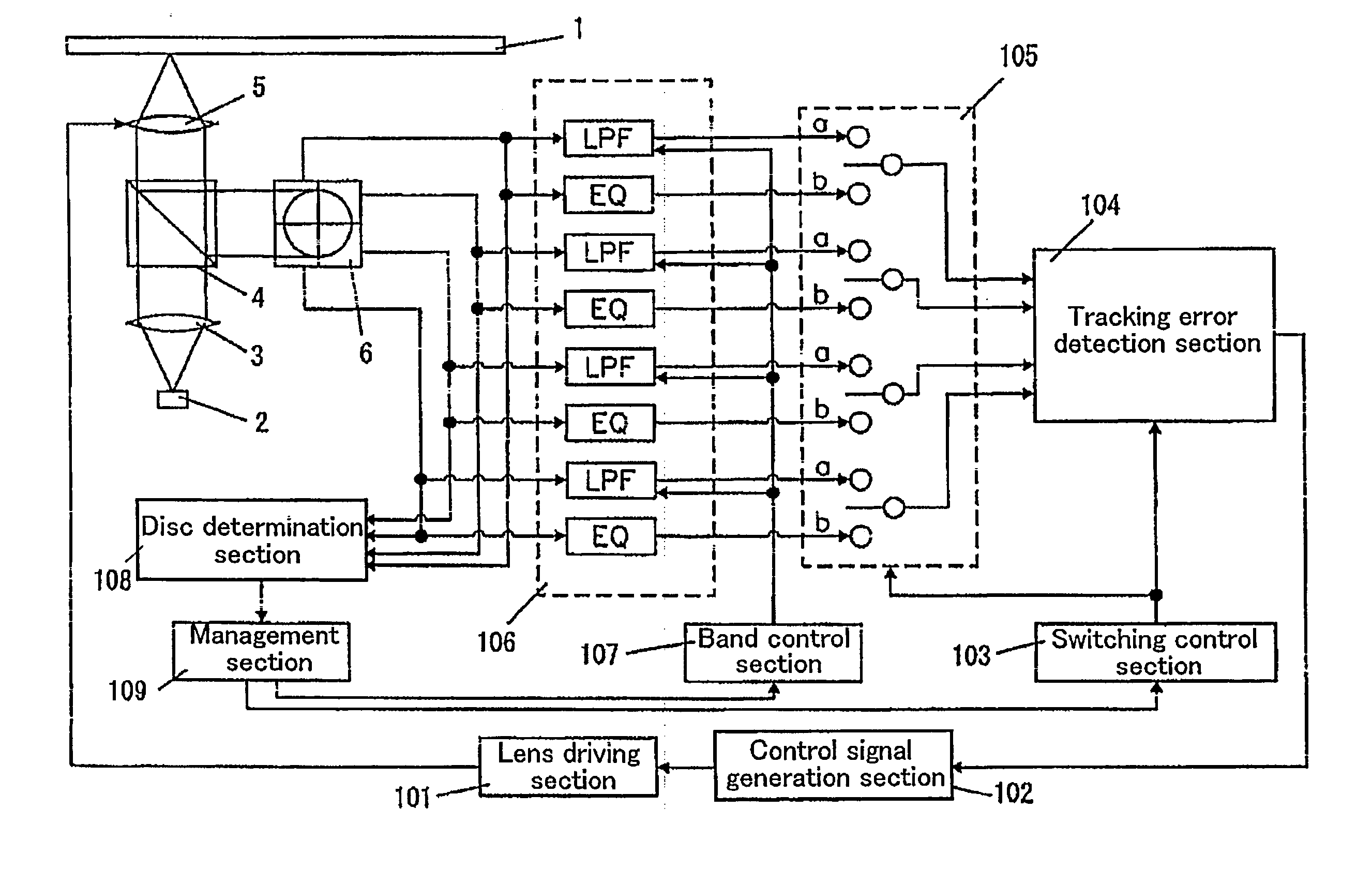
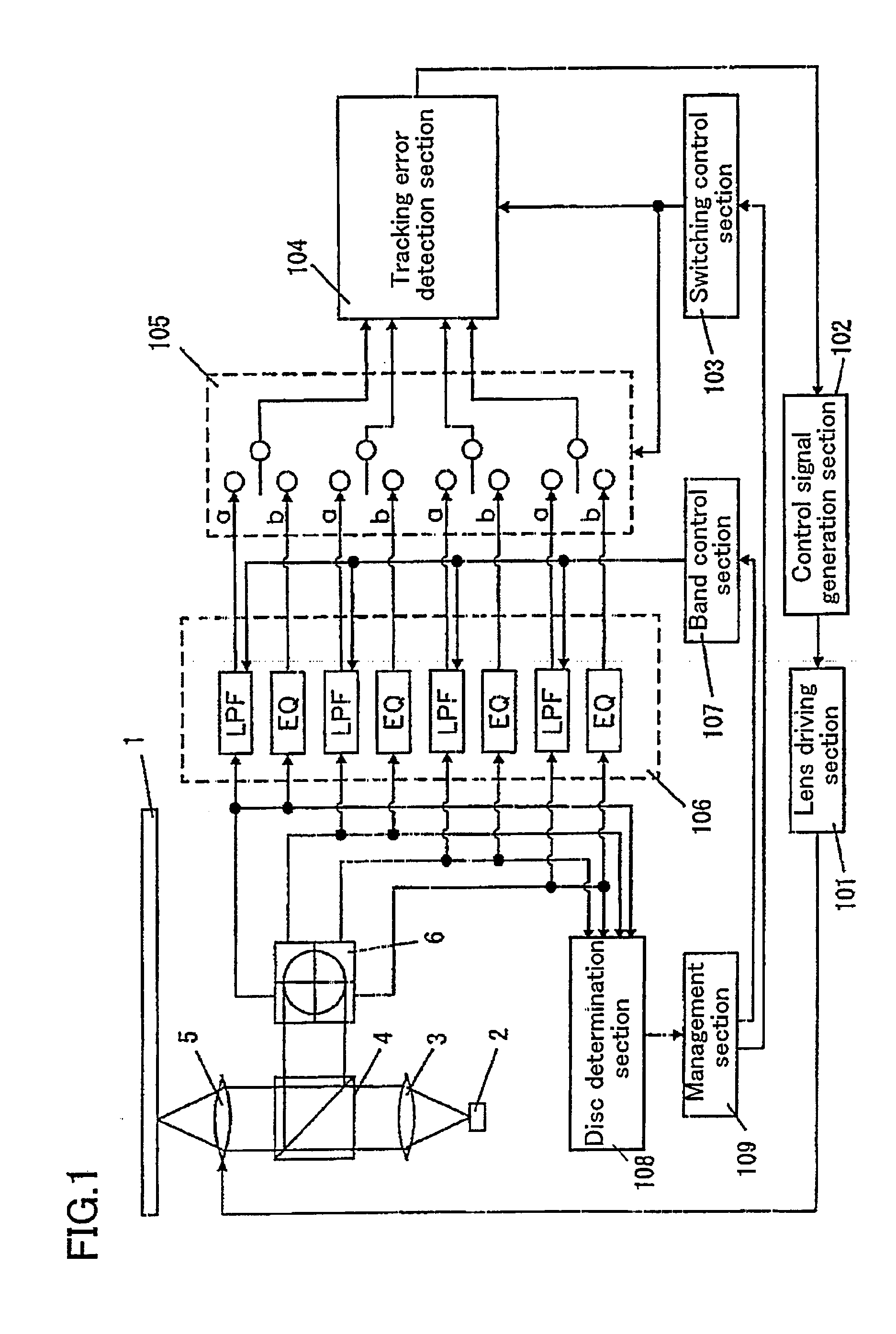
[0052]FIG. 1 shows a structure of an optical disc apparatus according to Embodiment 1 of the present invention.

[0053] A laser diode 2 outputs laser light.

[0054] A collimate lens 3 converts the light output from the laser diode 2 into parallel light.

[0055] A beam splitter 4 transmits the parallel light from the collimate lens 3 through an objective lens 5. The beam splitter 4 also separates parallel light from the objective lens 5 (light reflected off an optical disc 1) to a direction of a received light quantity detection section 6.

[0056] The objective lens 5 focuses the parallel light passed through the collimate lens 3 and the beam splitter 4 to a recording surface of the optical disc 1 and forms an optical beam spot on the recording surface of the optical disc 1. Further, the objective lens 5 converts the light reflected off the optical disc 1 into parallel light and passes the parallel light through the beam splitter 4.

[0057] A lens driving section 101 moves the optical bea...


PUM

PropertyMeasurementUnit
frequencyaaaaaaaaaa
frequencyaaaaaaaaaa
areasaaaaaaaaaa

Abstract

To improve a precision of tracking control. A tracking control apparatus includes a filter section (106) including a plurality of low-pass filters (LPFs). Each of the plurality of low-pass filters (LPFs) removes components having frequencies equal to or higher than a predetermined cutoff frequency from a corresponding received light quantity signal among a plurality of received light quantity signals output from light detection means (6). The tracking control apparatus includes: a tracking error detection section (104) for generating a tracking error signal indicating an amount of deviation of an optical beam spot from a track to be scanned on a recording surface of an optical disc by performing predetermined calculations with respect to a plurality of signals output from the filter section (106); and a tracking control section (102) for driving moving means (101) such that the optical beam spot follows the track on the recording surface of the optical disc in accordance with the tracking error signal.

Description

TECHNICAL FIELD [0001] The present invention relates to a tracking control apparatus and method which allow improving a precision of tracking control, and a signal processing apparatus. BACKGROUND ART [0002] Conventionally, one DVD recorder records or re-produces DVD media of a plurality of types. DVD media include DVD-RAMs which can be overwritten for several times, DVD-Rs which can be recorded but cannot be overwritten, DVD-ROMs of a reproduction-only type, and the like. Their physical standards are different from each other. Thus, an optimal method for detecting tracking errors is different for each of the DVD media. [0003] Conventionally, a “phase difference method” and a “push-pull method” are known as a method for detecting tracking errors. [0004] The phase difference method is a method for detecting tracking errors by utilizing changes in light quantity caused by pits or recording marks of optical discs. When, for example, DVD-ROMs and DVD-Rs are reproduced, the phase differe...

Claims


Application Information

Patent Timeline
Patent Type & Authority Applications(United States)
IPC IPC(8): G11B7/00G11B7/09G11B7/13
CPCG11B7/0906G11B7/09
Inventor TAKAHASHI, RIEWATANABE, KATSUYA
Owner PANASONIC CORP
Why Eureka
Try Eureka