Camshaft adjusting device

a technology of adjusting device and camshaft, which is applied in the direction of valve arrangement, machine/engine, mechanical apparatus, etc., can solve the problems of increasing manufacturing cycle time and manufacturing cost, and achieve the effect of convenient and economical manufacturing

Active Publication Date: 2015-03-26
SCHAEFFLER TECH AG & CO KG
View PDF1 Cites 3 Cited by
  • Summary
  • Abstract
  • Description
  • Claims
  • Application Information

AI Technical Summary

Benefits of technology

The invention is a camshaft adjusting device that is easy and inexpensive to manufacture and securely centers the camshaft or its adjuster on the camshaft. It achieves this by using a receiving bushing that must be manufactured with very precise tolerances to prevent imbalance when the camshaft is inserted. This disadvantageously increases manufacturing costs and cycle times. The device uses spacer elements that are manufactured separately and inserted into the receiving bushing, which ensures centering accuracy regardless of the remaining components of the camshaft adjuster. The spacer elements are tapered towards the camshaft to minimize contact points and prevent tilting or twisting of the camshaft when tightened. The indentations in the receiving bushing facilitate a flat contact of the camshaft, preventing damage to the camshaft. The spacer elements can be located on the inner lining of the receiving bushing and are calibrated to necessary tolerances. This simplifies manufacturing and ensures centering accuracy.

Problems solved by technology

This disadvantageously increases the costs and the cycle times for manufacturing.

Method used


Image

  • Camshaft adjusting device
  • Camshaft adjusting device
  • Camshaft adjusting device

Examples


Embodiment Construction

[0026]In the figures, the same elements are provided with the same reference numerals and described only once.

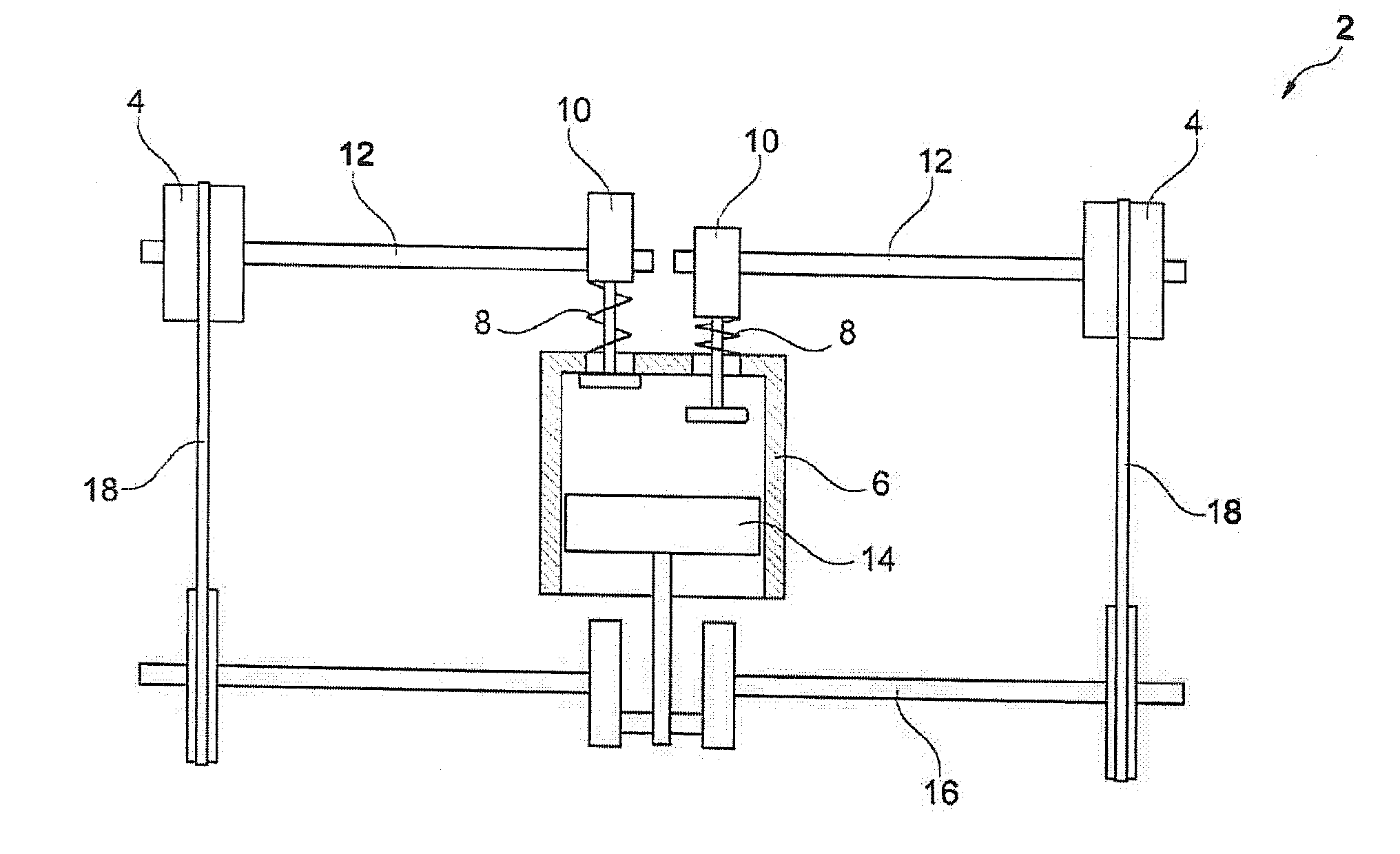
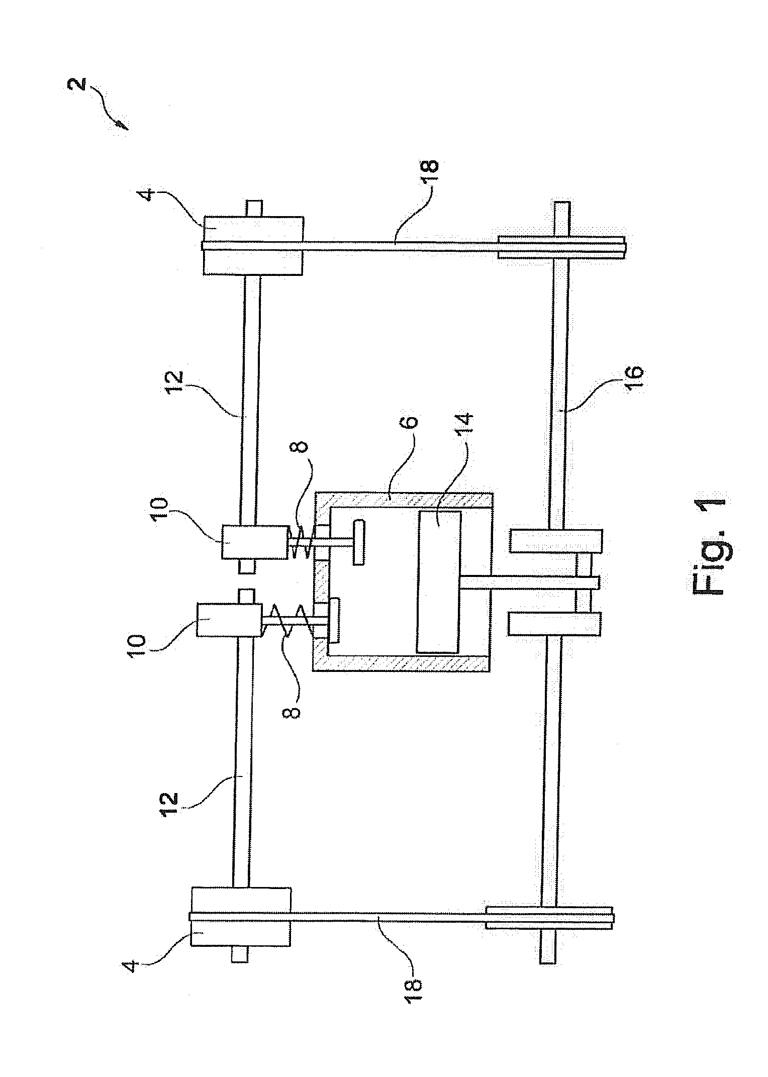
[0027]Reference is hereby made to FIG. 1, which shows a schematic representation of an internal combustion engine 2, including camshaft adjusters 4.

[0028]In a manner which is known per se, internal combustion engine 2 includes a combustion chamber 6, which may be opened and closed with the aid of valves 8. The valves are activated by cams 10 on corresponding camshafts 12. A reciprocating piston 14, which drives a crankshaft 16, is accommodated in combustion chamber 6. The rotation of crankshaft 16 is transmitted on its axial end to camshaft adjusters 4 via driving means 18. In the present example, the driving means may be a chain or a belt.

[0029]Camshaft adjusters 4 are each mounted axially on camshafts 12, absorb the rotation energy of driving means 18 and transfer it to camshafts 12. Camshaft adjusters 4 are thus able to temporarily decelerate or accelerate the rotation of...


PUM


Abstract

A camshaft adjusting device (19) having a camshaft adjuster (4), including a stator (36), a rotor (38) which can be rotated relative to the stator (36) about a rotational axis (74), and a hub (52) which is arranged on the rotor (38) or on the stator (36) and has a receiving cup (62), and having a camshaft (12) which is received in the receiving cup (62). It is provided here that the camshaft (12) is fixed radially in the receiving cup (62) via at least three spacer elements (64). A camshaft adjusting device (19) of this type can be produced simply and inexpensively.

Description

[0001]The present invention relates to a camshaft adjusting device having a camshaft adjuster, which includes a stator, a rotor which is rotatable relative to the stator around a rotation axis, and a hub situated on the rotor or on the stator and having a receiving bushing, as well as a camshaft accommodated in the receiving bushing. In particular, the present invention deals with the problem of centering the camshaft adjuster on the camshaft.BACKGROUND[0002]Via the hub, the camshaft adjuster of a camshaft adjusting device of the type mentioned at the outset is rotatably fixedly connected to the crankshaft of an internal combustion engine. The phase angle between the crankshaft and the camshaft may be set with the aid of the relative rotatability of the rotor relative to the stator.[0003]A camshaft adjusting device is known from DE 101 617 01 A1, in which the camshaft is accommodated in a receiving bushing in the rotor of the camshaft adjuster for the purpose of centering with the a...

Claims


Application Information

Patent Timeline
Patent Type & Authority Applications(United States)
IPC IPC(8): F01L1/344
CPCF01L1/344F01L1/047F01L1/3442F01L2303/00
Inventor WEBER, JUERGENHEINEMANN, ROBERT
Owner SCHAEFFLER TECH AG & CO KG
Why Eureka
Try Eureka