
Twist drill having at least two cutting inserts at the tip each with its own J-shaped chip guiding flute and a method for the production thereof

a technology of guiding flute and cutting insert, which is applied in the field of drills, can solve the problems of affecting the surface quality of the bore, forming different chip shapes, and helical chips and helical fragmental chips can also be produced,

Active Publication Date: 2012-11-27
KENNAMETAL INC
View PDF27 Cites 5 Cited by
  • Summary
  • Abstract
  • Description
  • Claims
  • Application Information

AI Technical Summary

Benefits of technology

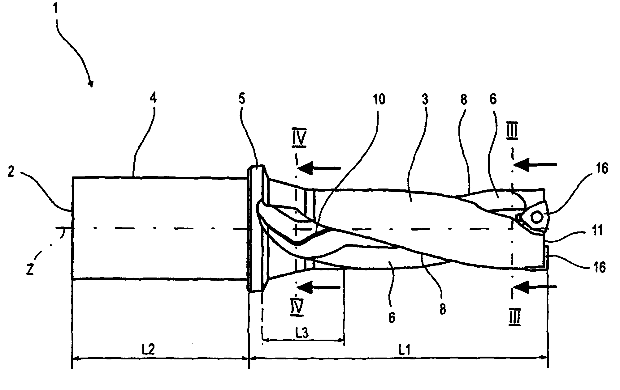
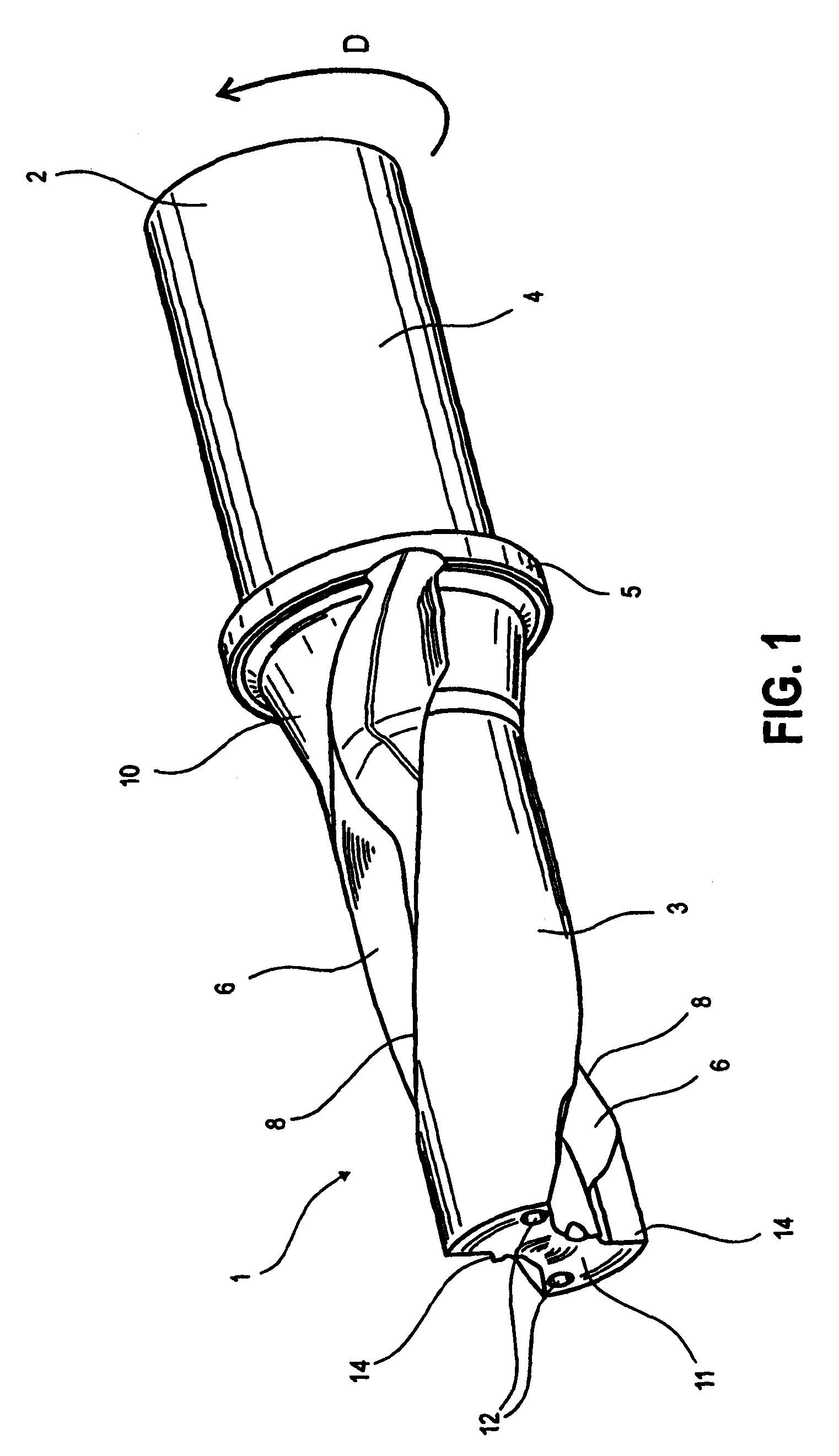
[0015]The resultant sickle-shaped form of the chip cavity constituted by the chip groove results in an improved chip guidance, since, owing to the acute advance angle, there is realized a kind of wedge that, as it were, scrapes the chip from the wall of the bore. At the same time, owing to the convex curvature and the concave fillet constituted thereby, the chip is guided securely into the chip groove, and held there. The risk of a chip becoming jammed between the drilling tool and the wall of the bore is therefore reduced. The curvature of the chip groove is also instrumental in the shaping of the chip, such that the latter can be taken away easily and reliably in the chip groove. At the same time, owing to the J-shaped form, the chip is held reliably in the chip cavity.
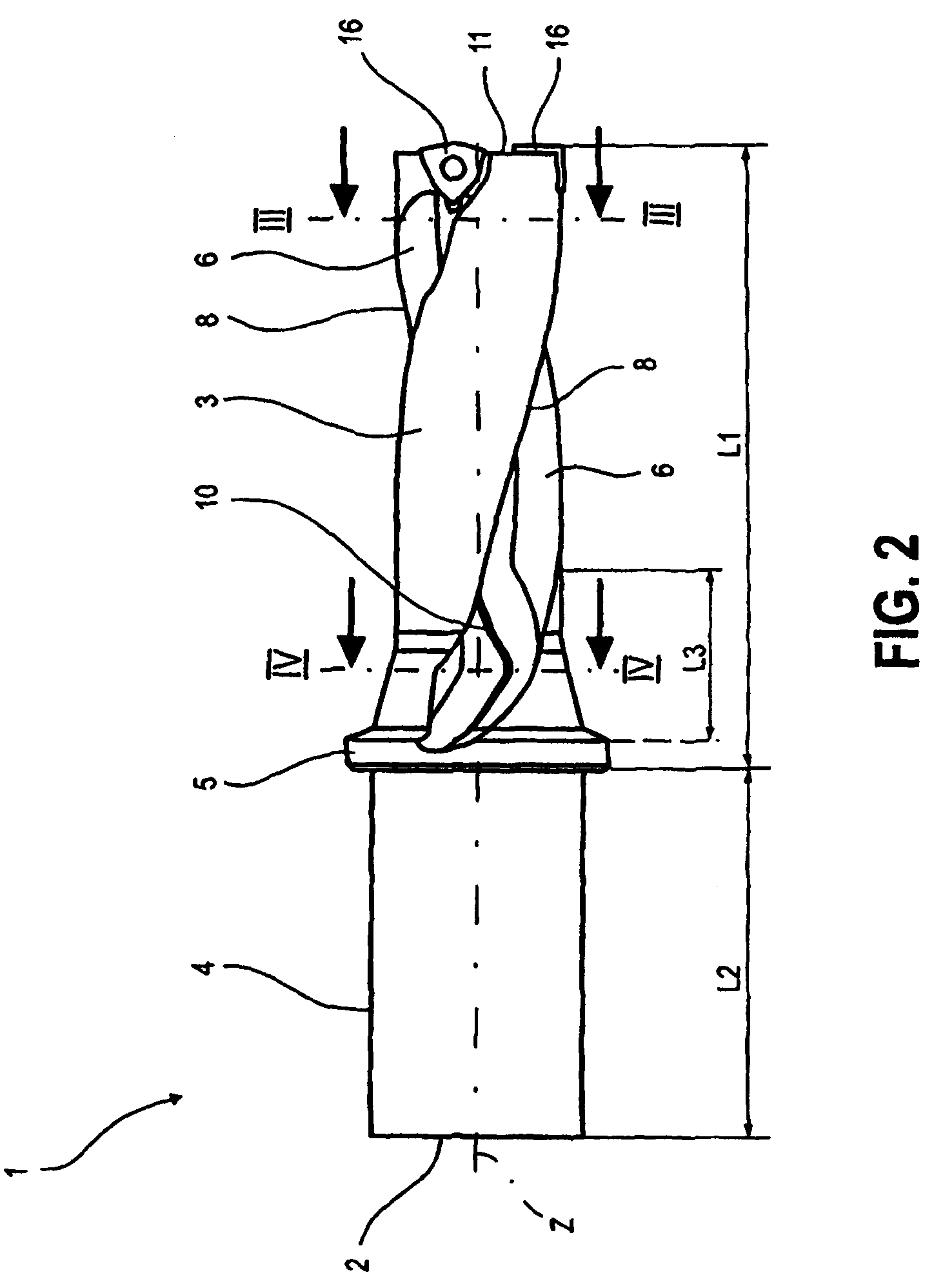
[0025]In one possible embodiment according to the present application, the chip groove is machined in a continuous operation, following the milling in the front region, in a run-out region adjoining the front region. In this case the milling cutter is in one possible embodiment swiveled in such a way that the advance angle is reduced, in one possible embodiment, to zero degrees. This measure results in the sickle-shaped form of the chip cavity, constituted by the concave fillet, undergoing transition to a straight run-out. That is to say, at least in the end region of the run-out region, the chip groove wall extends out rectilinearly, such that the chip can emerge easily from the chip groove. In this case, the milling cutter is swiveled appropriately in a simple manner. There is then essentially no need or desire for tool changing for alteration of the cross-sectional geometry, such that a rapid, inexpensive realization of the chip groove in one working step is rendered possible.

Problems solved by technology

Fluctuations of the parameters in the drilling process result in the formation of differing chip shapes.
In addition to the wanted fragmental chip pieces, unwanted helical chips and helical fragmental chips can also be produced.
These chip portions, when being removed from the cutting edge of the drilling tool via the chip groove, continually or substantially continually cause contact with the wall of the bore, resulting in scores that impair the surface quality of the bore produced.
Moreover, a continual or substantially continual occurrence is that, at the run-out edge, chips become jammed between the wall of the bore and the rear of the drill, and thereby cause increased torsional loading of the drill body.
Owing to the greatness of their length relative to their diameter, and to the cross-section being reduced by the chip groove, drilling tools are liable to deformations, including deflection, as a result of the forward-feed forces during the drilling operation.
The vibrations resulting therefrom reduce the quality of the bore.

Method used


Image

  • Twist drill having at least two cutting inserts at the tip each with its own J-shaped chip guiding flute and a method for the production thereof
  • Twist drill having at least two cutting inserts at the tip each with its own J-shaped chip guiding flute and a method for the production thereof
  • Twist drill having at least two cutting inserts at the tip each with its own J-shaped chip guiding flute and a method for the production thereof

Examples


Embodiment Construction

[0034]Parts that correspond to one another are denoted by the same references in the figures.

[0035]FIG. 1 shows a perspective view of a carrier body of a modular drilling tool 1, without a cutting unit. The carrier body 2 is divided into a front region 3 and a shank region 4. The two regions are separated by a shoulder 5, which constitutes a bearing-contact collar. In one possible embodiment, the front region 3 has two chip grooves 6, which extend helically, diametrically opposite one another, in the front region 3. Viewed in the direction of rotation D of the drill, the chip groove 6 is in each case adjoined at the end by a run-out edge 8, which likewise extends helically, corresponding to the chip groove 6. Provided towards the shank region 4 is a run-out region 10, in which the chip groove 6 runs out of the carrier body 2, along the shoulder 5. The carrier body 2 additionally has a coolant bore 12 that corresponds, respectively, to each of the chip grooves 6, the openings of whic...


PUM

PropertyMeasurementUnit
acute angleaaaaaaaaaa

Abstract

A twist drill having at least two cutting inserts at the tip each with its own J-shaped chip guiding flute and a method for the production thereof.

Description

CONTINUING APPLICATION DATA[0001]This application is a Continuation-In-Part application of International Patent Application No. PCT / EP2007 / 008407, filed on Sep. 27, 2007, which claims priority from Federal Republic of Germany Patent Application No. 10 2006 049 088.6, filed on Oct. 13, 2006. International Patent Application No. PCT / EP2007 / 008407 was pending as of the filing date of this application. The United States was an elected state in International Patent Application No. PCT / EP2007 / 008407.BACKGROUND[0002]1. Technical Field[0003]The present application relates to a drill and a method for the production thereof.[0004]2. Background Information[0005]Background information is for informational purposes only and does not necessarily admit that subsequently mentioned information and publications are prior art.[0006]The present application relates to a modular drilling tool, comprising a carrier body and a cutting unit that can be fastened thereto, the carrier body extending along a ca...

Claims


Application Information

Patent Timeline
Patent Type & Authority Patents(United States)
IPC IPC(8): B23B51/02
CPCB23B47/34B23B51/048B23B51/02B23C3/32B23B2265/08B23B2270/30B23B2251/04B23B2251/404B23B2251/408Y10T408/90993Y10T408/455B23B2251/406Y10T409/303808Y10T408/9097B23B51/00B23B51/04B23C3/36
Inventor MERGENTHALER, PETER KARL
Owner KENNAMETAL INC
Learn More