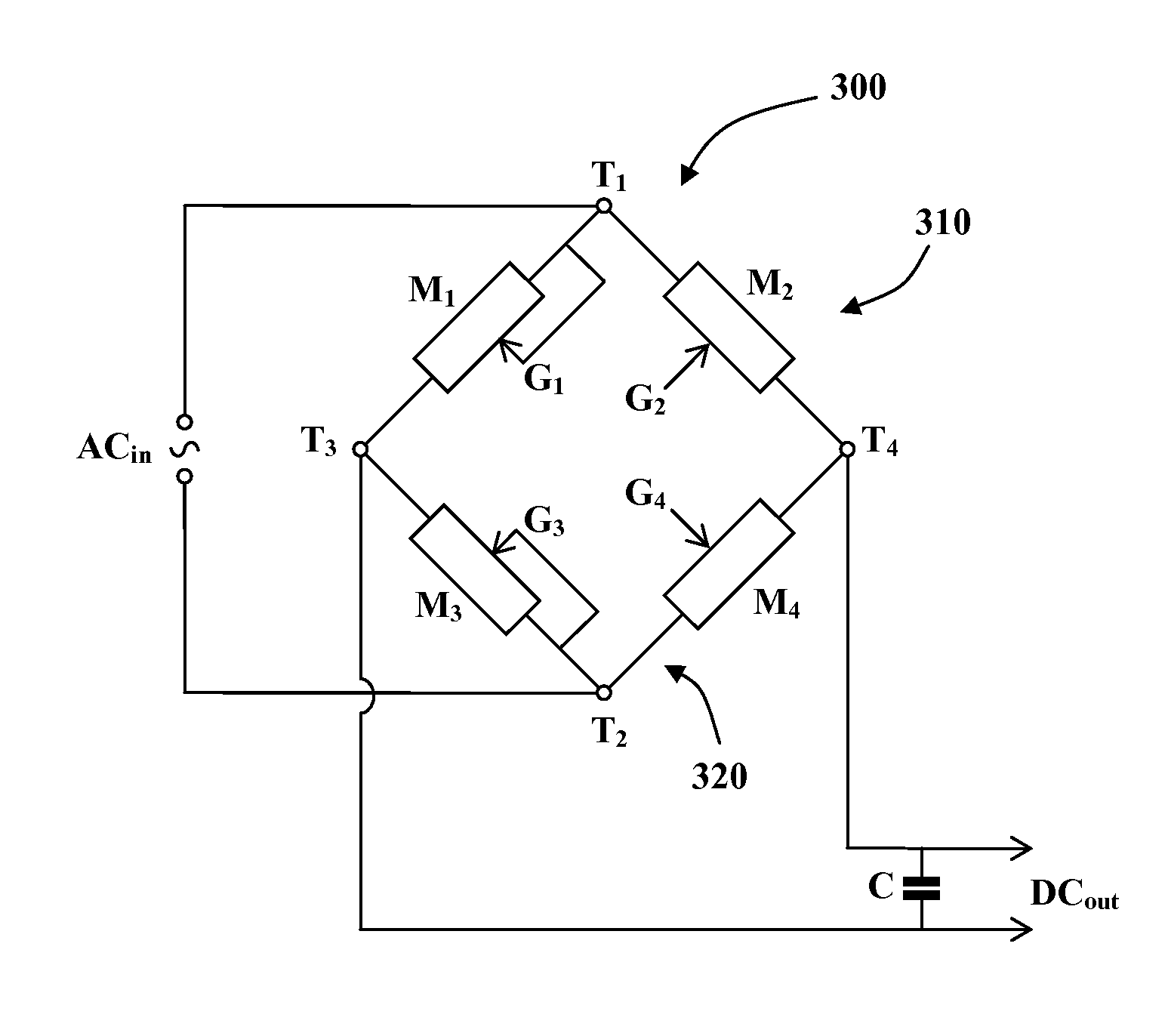
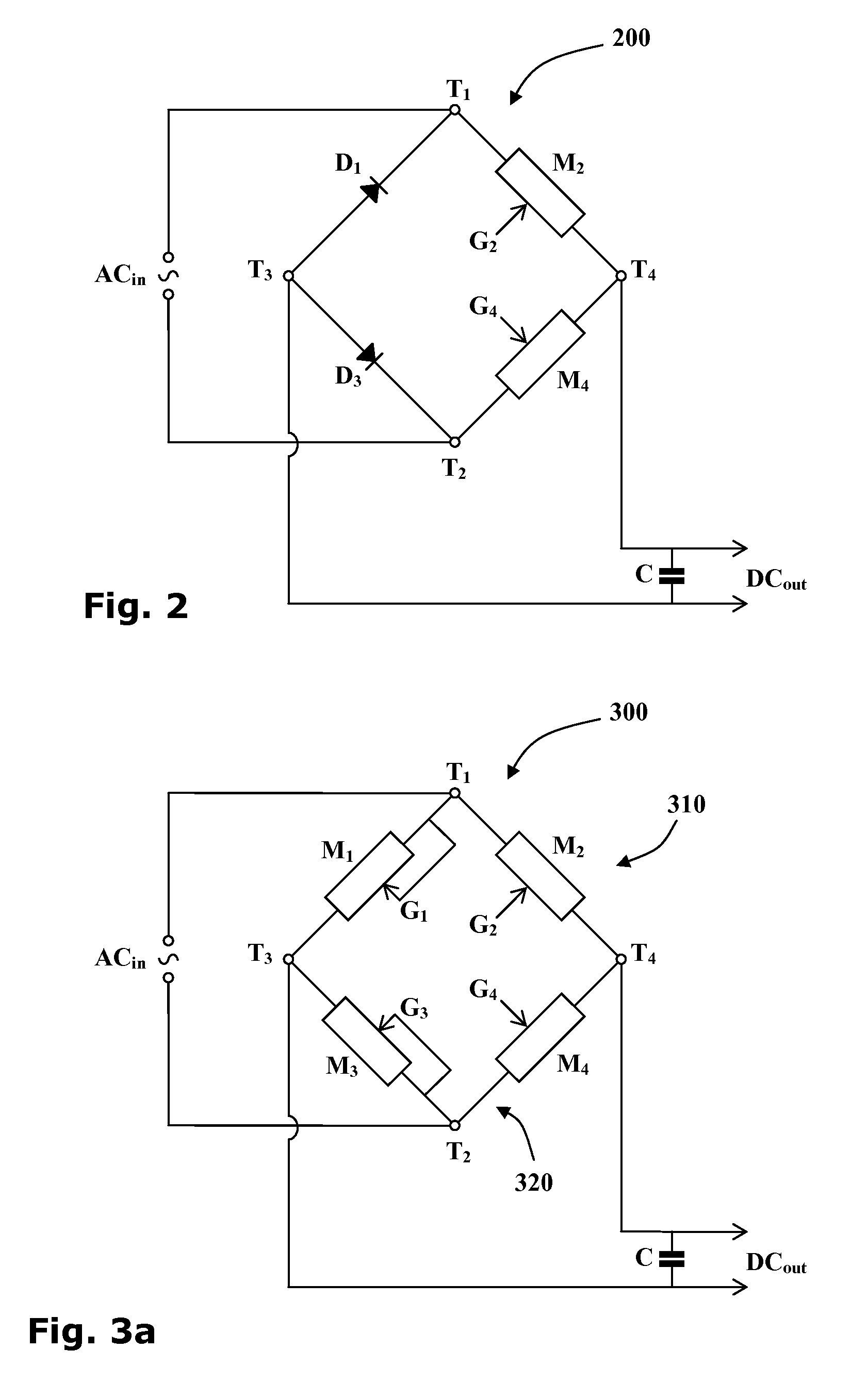
Bridge synchronous rectifier
a bridge rectifier and synchronous technology, applied in the field of full-wave rectifiers, can solve the problems of ineffective diodes, forward voltage drop, and inefficiency of diodes
- Summary
- Abstract
- Description
- Claims
- Application Information
AI Technical Summary
Problems solved by technology
Method used
Image
Examples
Embodiment Construction
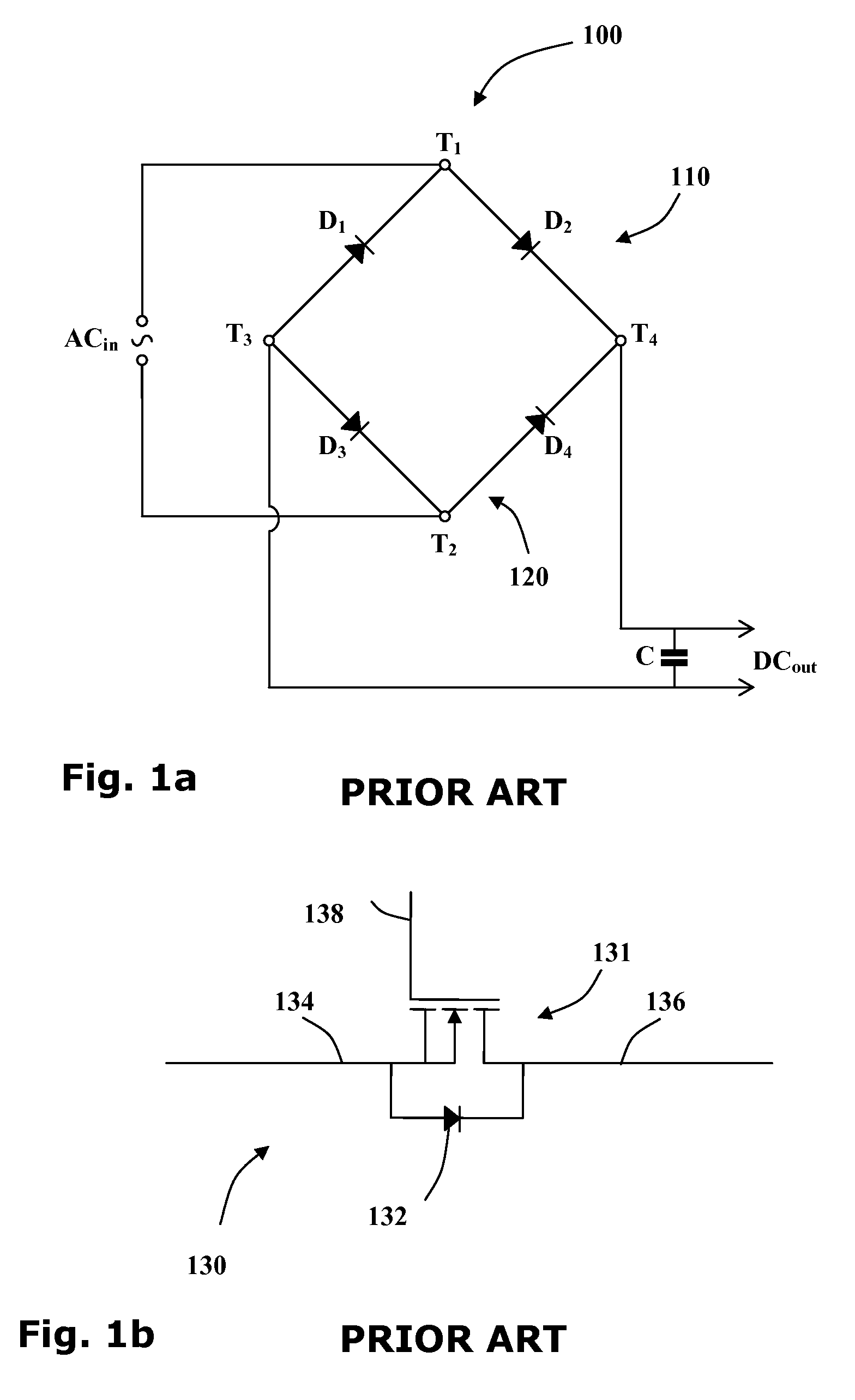
[0051]Reference is now made to FIG. 1a showing a circuit diagram of a typical full-wave rectifier 100 of the prior art. The rectifier has two input terminals T1 and T2 and two output terminals T3 and T4. When an alternating current source ACin is wired to the two input terminals T1 and T2, a direct current output DCout may be drawn from the two output terminals T3 and T4 of the rectifier 100.
[0052]Four diodes D1-4 are arranged so that two diodes D1 and D2 form a first branch 110 of a Graetz circuit and the other two diodes D3 and D4 form a second branch 120 of the Graetz circuit. The anodes of two upstream diodes D1 and D3 are wired to the first output terminal T3 and the cathodes of the two downstream diodes D2 and D4 are wired to the second output terminal T4. The cathode of the first upstream diode D1 and the anode of first downstream diode D2 are wired to the first input terminal T1 and the cathode of the second upstream diode D3 and the anode of second downstream diode D4 are w...
PUM
 Abstract
Description
Claims
Application Information
 - R&D
- Intellectual Property
- Life Sciences
- Materials
- Tech Scout
- Unparalleled Data Quality
- Higher Quality Content
- 60% Fewer Hallucinations
Browse by: Latest US Patents, China's latest patents, Technical Efficacy Thesaurus, Application Domain, Technology Topic, Popular Technical Reports.
© 2025 PatSnap. All rights reserved.Legal|Privacy policy|Modern Slavery Act Transparency Statement|Sitemap|About US| Contact US: help@patsnap.com


