Fastening device

a technology of fastening device and clip, which is applied in the direction of snap fasteners, buckles, transportation and packaging, etc., can solve the problems of design unsuitability for fastening decorative trim parts and clip unsuitability for flat trim parts, so as to facilitate the introduction of connecting parts

Active Publication Date: 2012-12-04
NEWFREY
View PDF35 Cites 39 Cited by
  • Summary
  • Abstract
  • Description
  • Claims
  • Application Information

AI Technical Summary

Benefits of technology

[0007]According to one aspect of the invention, a fastener for fastening attached parts or trim parts does not require fastening openings in the parts that are to be joined together. The fastener may be simple to install and may consist of simple parts that can be manufactured inexpensively. It may also provide the capability to compensate for manufacturing-related dimensional variations, but may also be suitable for providing a fixed mounting point. Lastly, it may be possible to separate the parts joined by the fastener without damage.
[0010]According to a further proposal of the invention, the fastening section of the connecting part is designed as a hollow body, wherein one end of the hollow body is attached to the flange, and the other end has an insertion opening for a retaining stud, and wherein the retaining means for holding the retaining stud in place are located on the inside of the hollow body. The wall of the hollow body preferably consists of cylindrical wall sections and of fluted wall sections that are located between the cylindrical wall sections and that have the raised side of their flute profile projecting into the hollow body. This design permits guidance of the fastening section into the guide slot of the receptacle part with the aid of the cylindrical wall sections with simultaneous guidance and centering of the retaining stud in the interior of the hollow body with the aid of the fluted wall sections. To facilitate the insertion and centering of the retaining stud relative to the fastening section even in the presence of lateral offset of the fastening section relative to the retaining stud, provision can additionally be made for the end faces of the fluted wall sections to be beveled in the vicinity of the insertion opening so as to form guide surfaces inclined in the insertion direction.
[0014]In order to secure the connecting part against falling out after placement in the receptacle part, the plate of the receptacle part may be additionally provided with at least one raised bump that is located opposite the cover plate and has a distance therefrom that is slightly smaller than the thickness of the flange of the connecting part. The bump provides a resistance that can be overcome with light force but that is sufficient to keep the connecting part from coming out by itself once placed in the pocket. The introduction of the connecting part can be further eased by additional ramps on the insertion side of the bump.

Problems solved by technology

It is a disadvantage here that the support part must have openings at the fastening points and that additional means such as a dished washer and possibly additional sealing rings must be provided so that these openings can be tightly sealed during installation of the attached parts or trim parts.
Such a design is unsuitable for fastening decorative trim parts.
Such a clip is also unsuitable for fastening flat trim parts.

Method used


Image

  • Fastening device
  • Fastening device
  • Fastening device

Examples


Embodiment Construction

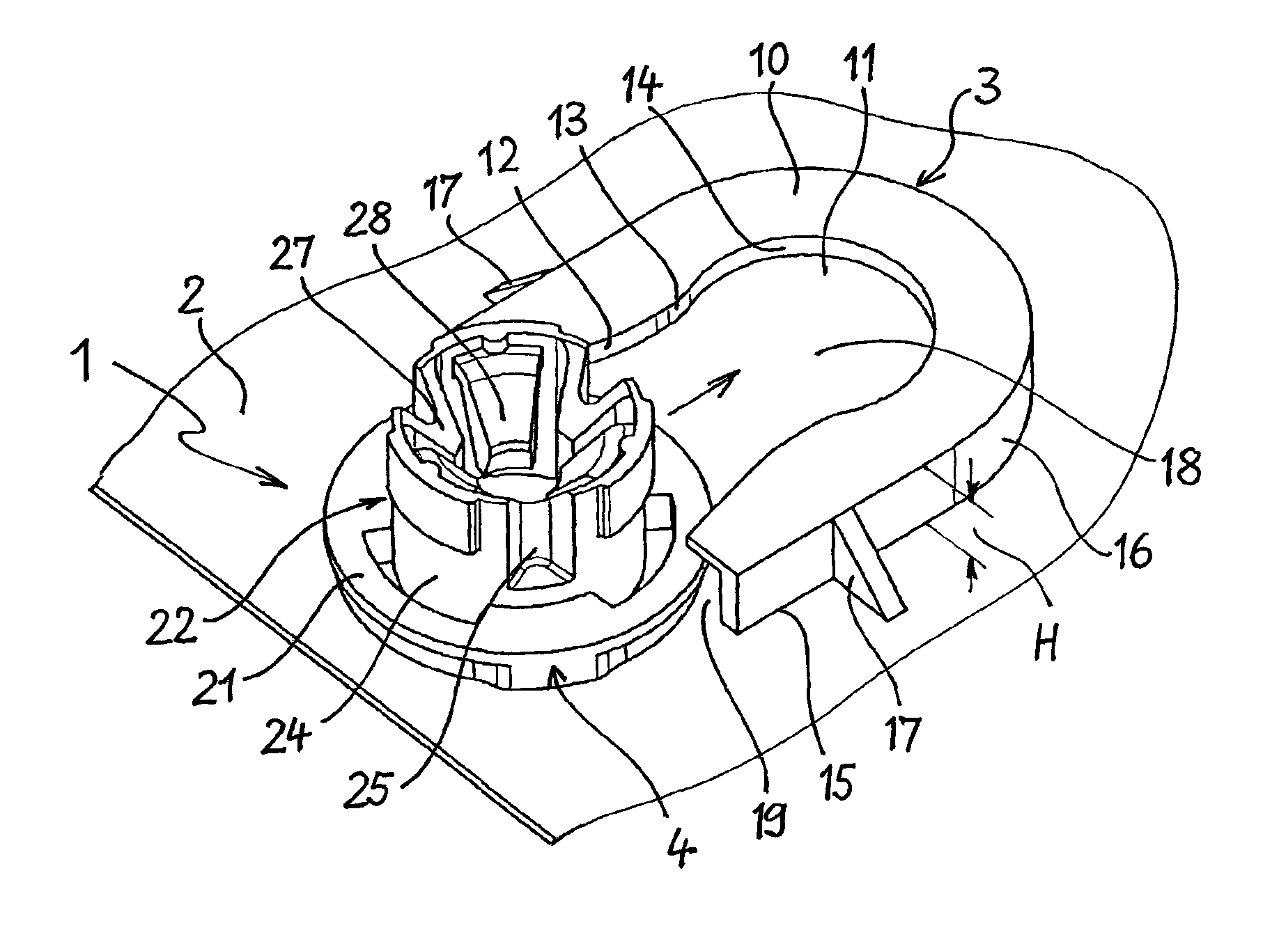
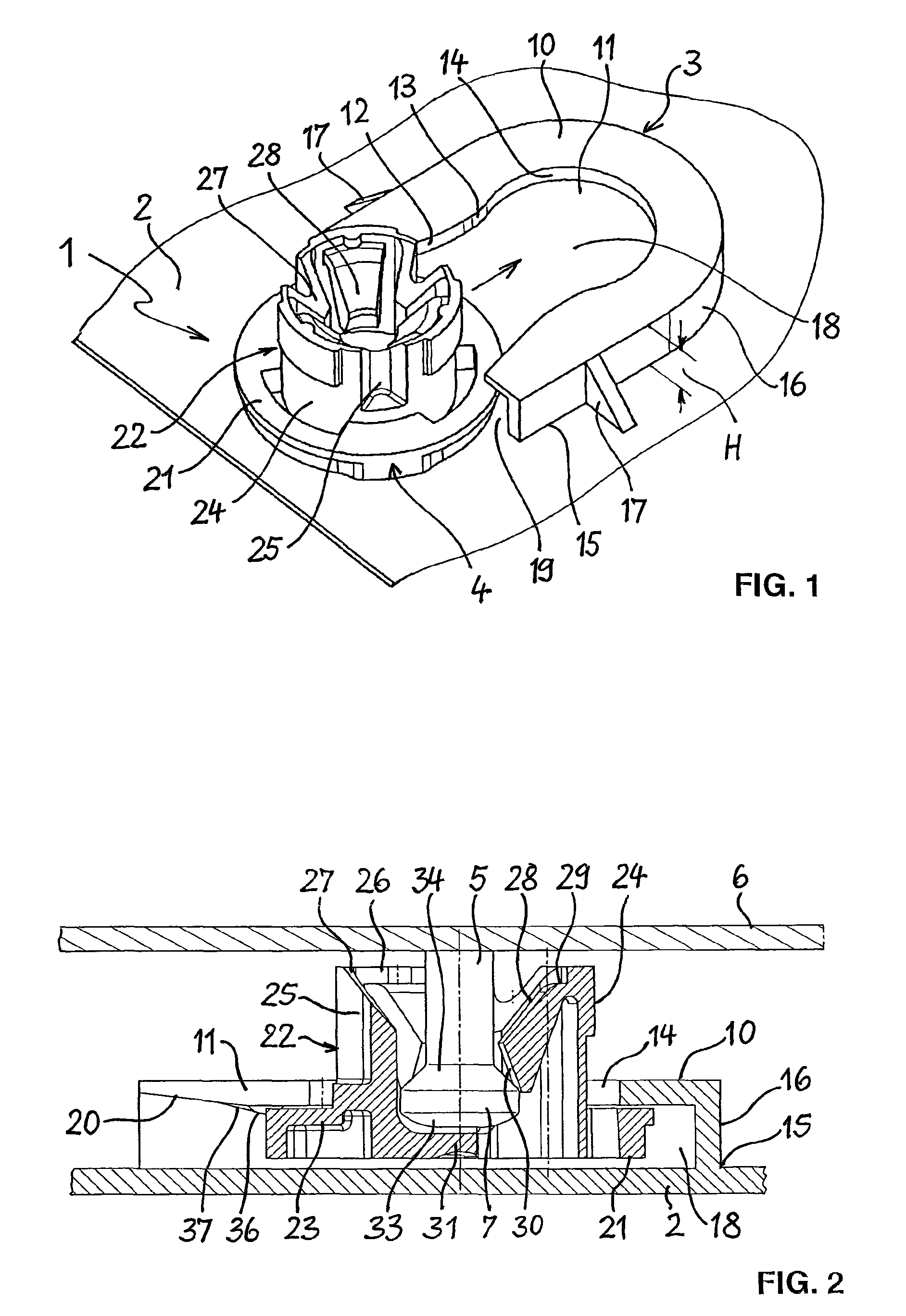
[0022]The fastener 1 shown in FIGS. 1 and 2 includes a receptacle part 3 fastened to a panel-like trim part 2, a connecting part 4, and a T-shaped retaining stud 5 that is attached to a support part 6 and has a head 7 at its free end. The trim part 2, the receptacle part 3, and the connecting part 4 are made of thermoplastic material. The retaining stud 5 and the support part 6 are made of metal and are welded to one another. However, the invention is not limited to the use of the stated materials. The trim part and receptacle part may be made of metal, and the support part and retaining stud may be made of plastic.

[0023]The receptacle part 3 has a flat plate 10 with a guide slot 11, which forms an entry region 12 that enlarges conically towards the edge of the plate, a narrow point 13, and a circular end region 14 whose diameter is larger than the width of the narrow point 13. Extending along the outer edge 15 of the plate 10 is a U-shaped wall 16, which surrounds the guide slot 11...


PUM


Abstract

A fastener for fastening an attached or trim part to a support part includes a receptacle part having a pocket with a lateral opening and a guide slot, and a connecting part having at least one flange that can be introduced into the pocket through the lateral opening and having a fastening section. The fastening section has an opening to accommodate a retaining stud projecting from the support part. Located in the opening are latching fingers which can hold the retaining stud in place in the opening.

Description

CROSS-REFERENCE TO RELATED APPLICATIONS[0001]This application claims priority from German Patent Application No. 10 2008 033 307.7, filed on Jul. 16, 2008, the disclosure of which is incorporated herein by reference.FIELD OF THE INVENTION[0002]The invention relates to a fastener for fastening an attached part or trim part to a support part, in particular a body part of a motor vehicle, with a receptacle part that has a pocket with a lateral opening and a guide slot, and with a connecting part that has at least one flange that can be introduced into the pocket through the lateral opening.[0003]Fasteners of the specified type are used primarily in automotive manufacture for fastening trim parts and attached parts to the vehicle body or to body parts such as doors and the like. It is often advantageous to provide fastening in the simplest possible manner and without the aid of tools, and there is frequently a need to be able to compensate for dimensional variations of the parts in the ...

Claims


Application Information

Patent Timeline
Patent Type & Authority Patents(United States)
IPC IPC(8): F16B21/09B60R13/02
CPCB60R13/0206B60R13/04F16B5/065F16B5/0657F16B5/123F16B21/073F16B5/126Y10T24/44017Y10T24/45775Y10T24/45874Y10T24/30
Inventor EHRHARDT, THOMASHAHN, ERNST LUDWIGSCHAETY, HARALD
Owner NEWFREY
Why Eureka
Try Eureka