
Apparatus for connecting tubular cores

a technology of tubular cores and accessories, applied in the direction of mechanical control devices, instruments, process and machine control, etc., can solve the problems of creating joints and inability to align the cores, and achieve the effect of high precision and increased core alignment precision

Active Publication Date: 2012-12-04
GA VO MECCANICA SNC
View PDF11 Cites 0 Cited by
  • Summary
  • Abstract
  • Description
  • Claims
  • Application Information

AI Technical Summary

Benefits of technology

[0008]Another feature of the invention is to provide an apparatus for feeding the cores that has a core feeding system that assists loading the cores and ensures that only one core at a time is loaded.
[0010]A further feature of the invention is to provide an apparatus for feeding the cores that allows a completely automatic operation of the joints and of the cut for any diameter of the cores.
[0056]Advantageously, in said cutting station means are provided for reversing the speed of rotation of the core during the cut after that the core has rotated of a predetermined angle. This way, it is possible to obtain a very high cut finishing.

Problems solved by technology

The drawback of this known system is that it is not possible to evaluate exactly the number of turns of adhesive tape wound about the cores, thus creating joints always different from each other and then with different resistance characteristics.

Method used


Image

  • Apparatus for connecting tubular cores
  • Apparatus for connecting tubular cores
  • Apparatus for connecting tubular cores

Examples


Embodiment Construction

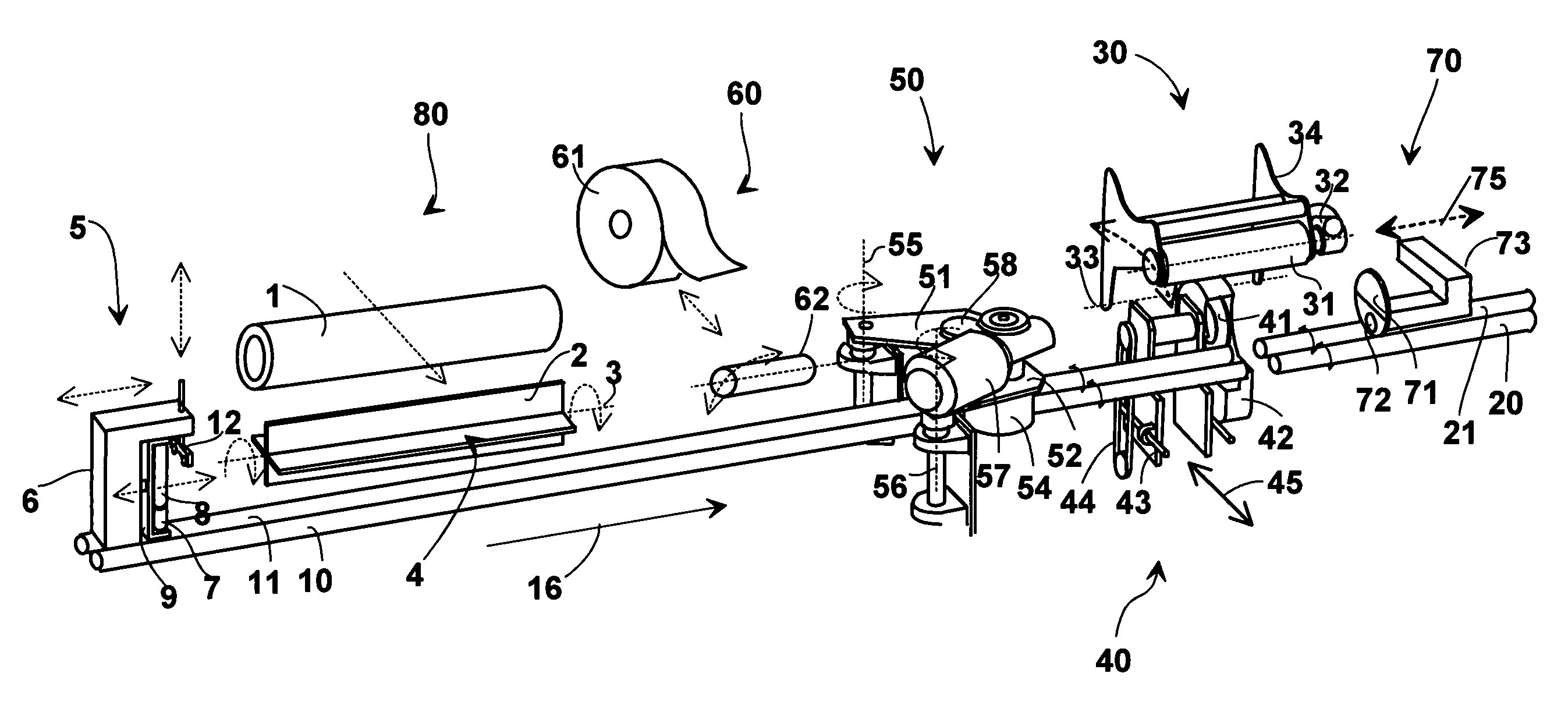
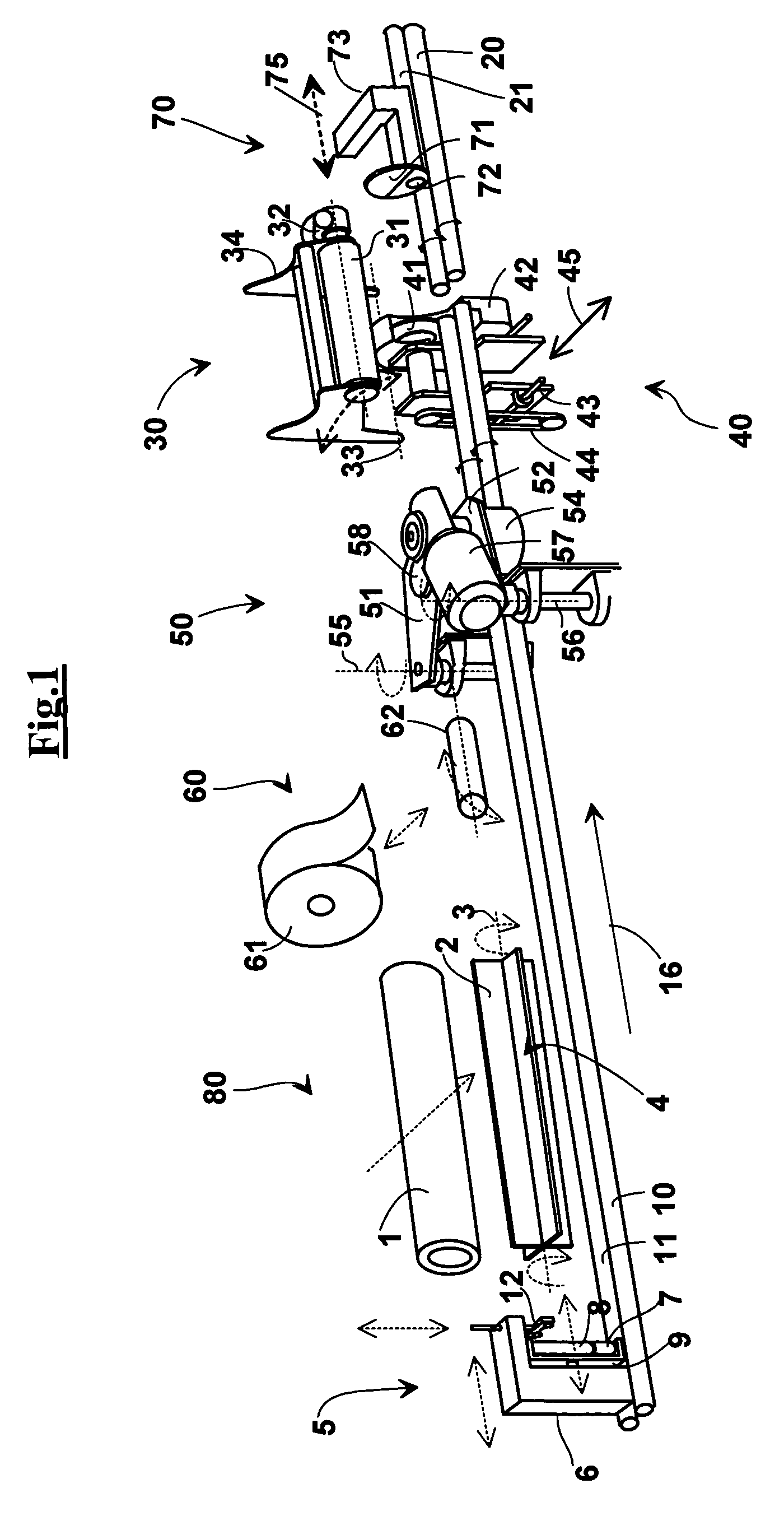
[0095]With reference to FIG. 1, an apparatus is described for connecting and cutting tubular cores 1 for supporting rolls of wound material. Such an apparatus comprises a loading station 80, having core feeding means 1 adapted to position a core at a time on a rolling cradle consisting of two parallel and horizontal rollers 10 and 11. The feeding means comprises a star-shaped driven supplier 4, having, for example, four continuous protrusions 2 that allow to load tubular cores of different lengths. The fact that the protrusions 2 are continuous allows loading tubular cores 1 of lengths that must be from a few centimeters up to the maximum length, without manual adjustment.

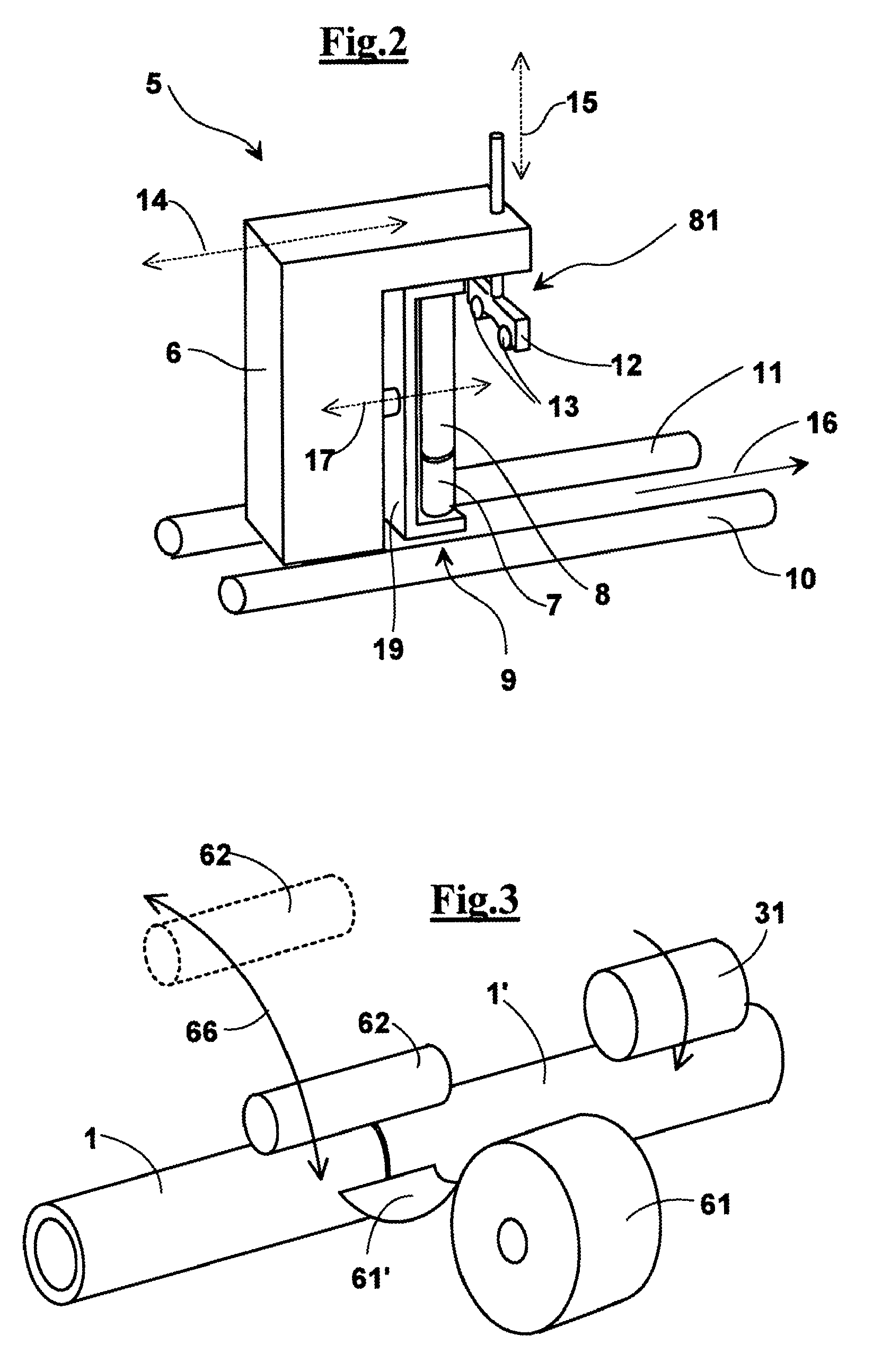
[0096]The rollers 10 and 11 of the rolling cradle are arranged along a longitudinal direction 16, as also the axis of the cores during the work and the handling direction the cores same. The apparatus comprises means for pushing cores 1 along the longitudinal direction 16, in particular, a pusher 5 that acts agains...


PUM

PropertyMeasurementUnit
angleaaaaaaaaaa
angleaaaaaaaaaa
lengthaaaaaaaaaa

Abstract

An apparatus for connecting and cutting tubular cores (1) for supporting rolls of wound material comprising a loading station (80), comprising a rolling cradle consisting of two parallel and horizontal rollers (10 and 11), a star-shaped driven supplier (4), having, for example, four continuous protrusions (2) that allow to load tubular cores of different lengths. The rollers (10 and 11) of the rolling cradle are arranged along a longitudinal direction (16). The apparatus comprises a pusher (5) that acts against a rear end of the core (1), once it has been loaded on the rolling cradle (10, 11), in order to bring a front end of a loaded core in a connecting station (60) where it is present the rear end of a core portion to connect, loaded previously. The pusher (5) comprises an approaching element (9) with vertical idle rollers (7 and 8). Downstream of the loading station (80) a taping station (60) is present and a transmission roller (62) bridging the two cores is capable of transmitting the moving rotation between the core portion and the core. A conveying station (50) a cutting station (30) and a sliding suction abutment (70) are present downstream. The apparatus has the peripheral dragging means (30) equipped with a device for transmitting a number of rotations suitable for causing said core and said core portion to rotate for a predetermined number of turns.

Description

FIELD OF THE INVENTION[0001]The present invention relates to a machine capable of connecting two tubular cores arranged in succession with facing ends and to cut a resulting jointed core according to a desired length.DESCRIPTION OF THE TECHNICAL PROBLEM[0002]Machines are known capable of connecting to each other two tubular cores arranged in succession with facing ends so that a front end of a previous core is arranged against a rear end of a next core, and such that a butt joint is formed by winding one or more layers of adhesive tape. The step of winding the adhesive tape is carried out approaching a free end thereof bridging the two adjacent cores in turn, at the butt joint. Then, the core downstream is caused to rotate, and its movement is transmitted to core upstream by an idle rubber roller arranged bridging the two cores, such that the two cores rotate about themselves dragging the adhesive tape and creating the butt joint.[0003]The drawback of this known system is that it is...

Claims


Application Information

Patent Timeline
Patent Type & Authority Patents(United States)
IPC IPC(8): B32B38/00B65C9/06B65C9/04B65C3/16B65C3/12B32B38/04
CPCB26D3/16B29C66/5221B65H75/505B29C65/5092Y10T156/12B29C66/1142B29C2793/009B29K2027/06B29C65/5042Y10T156/1322Y10T156/1317B29C65/5021Y10T156/1348Y10T156/1343B29C65/00B29C66/83413B29C66/71B29C66/8221Y10T83/2092Y10T83/2096Y10T83/2098
Inventor TANCREDI, ANTONIOBENVENUTI, STEFANONICCOLAI, ALESSANDRO
Owner GA VO MECCANICA SNC
Learn More