Weapons platform construction

a technology of weapons platforms and platforms, applied in the direction of offensive equipment, ammunition loading, transportation and packaging, etc., can solve the problems of inability to provide a missile launch capability, inability to provide a weapon system, and inability to meet the requirements of the target,

Inactive Publication Date: 2007-04-24
DEFENDTEX
View PDF20 Cites 3 Cited by
  • Summary
  • Abstract
  • Description
  • Claims
  • Application Information

AI Technical Summary

Benefits of technology

[0009]In one broad form, the present invention resides in a compact weapons platform including a plurality of barrel assemblies wherein the barrel assemblies form both weapons and structural members of the weapons platform. Suitably, barrels of said barrel assemblies are each formed from a relatively lightweight tube, preferably composed of composite materials such as engineered plastics or carbon fibre composites. If required, the tubes may be combined in a common walled cellular construction. Preferably, the barrel assemblies are arranged for firing projectiles simultaneously from opposed ends of the barrel in order to minimise undesirable recoil effect.
[0011]In another form the invention resides in a method of construction of a weapons platform, said method including the step of forming one or more structural members of the weapons platform from a plurality of barrel assemblies of a weapon. Suitably, the barrel assemblies are arranged with barrels directed in opposite directions in order to minimise undesirable recoil effect upon firing.
[0014]The projectile charge is located in the propellant space and may be formed as a solid block to assist in loading the barrel assemblies. Alternatively the propellant charge may be encased and may include an embedded primer having external contact means adapted for contacting a pre-positioned electrical contact associated with the barrel. For example the primer could be provided with a sprung contact which may be retracted to enable insertion of the cased charge into the barrel and to spring out into a barrel aperture upon alignment with that aperture for operative contact with its mating barrel contact. If desired the outer case may be consumable or may chemically assist the propellant burn. Furthermore an assembly of stacked and bonded or separate cased charges and projectiles may be provided to facilitate the reloading of a barrel.
[0018]Ignition of the propellant may be achieved electrically or ignition may utilise conventional firing pin type methods such as by using a centre-fire primer igniting the outermost projectile and controlled consequent ignition causing sequential ignition of the propellant charge of subsequent rounds. This may be achieved by controlled rearward leakage of combustion gases or controlled burning of fuse columns extending through the projectiles or the barrel.

Problems solved by technology

In the case of small compact vehicles, the choice of weapons systems available may be practically limited or even obviated.
Many existing vehicles, particularly those in the nature of compact surveillance aircraft or investigatory robots, are typically relatively slow moving, operate at low altitude and are often unarmed, and consequentially susceptible to small arms fire.
However, it is clearly not viable to provide a missile launch capability as proposed for small compact vehicles of the kind particularly suited to the present invention.

Method used


Image

  • Weapons platform construction
  • Weapons platform construction
  • Weapons platform construction

Examples


Embodiment Construction

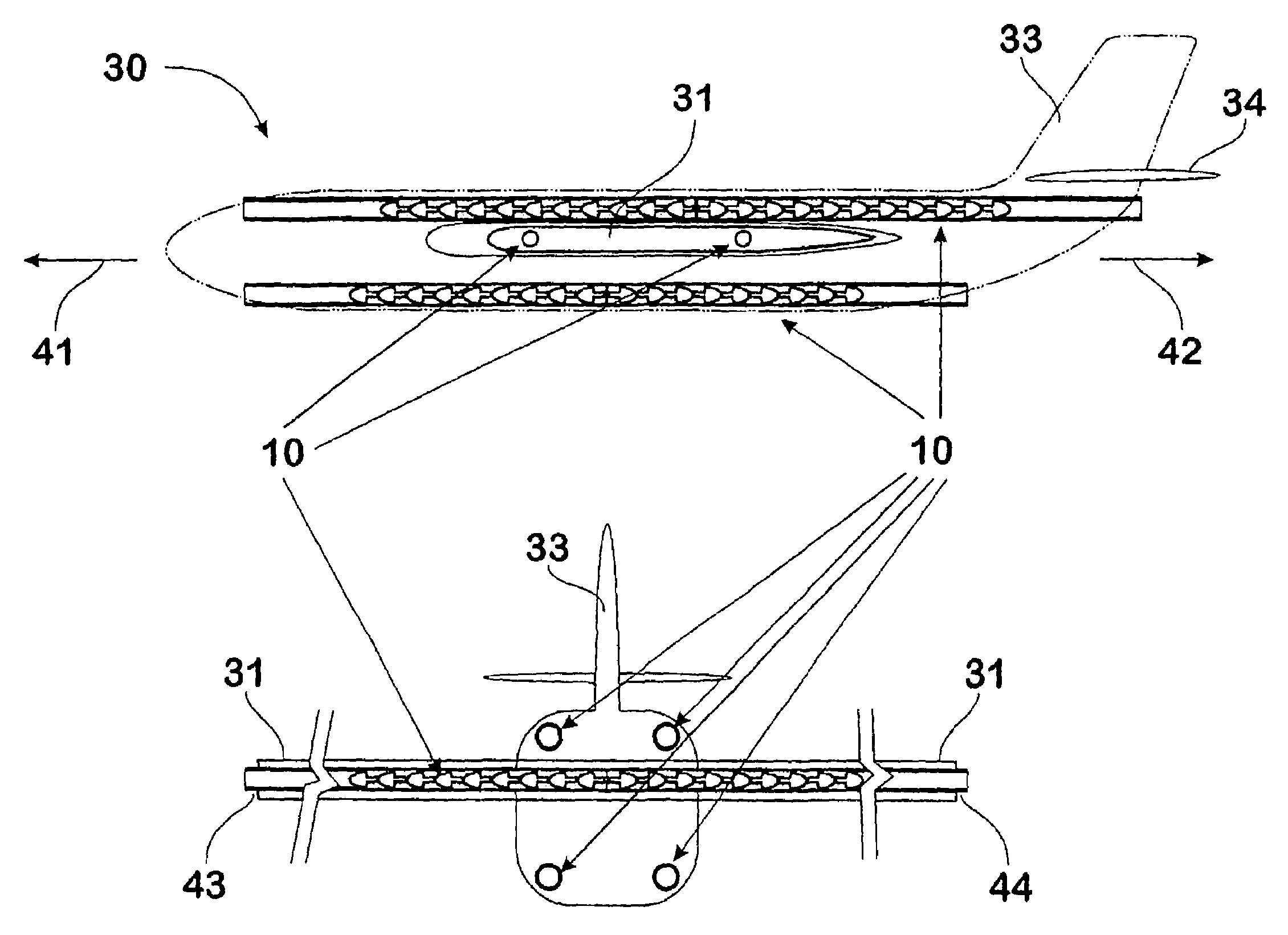
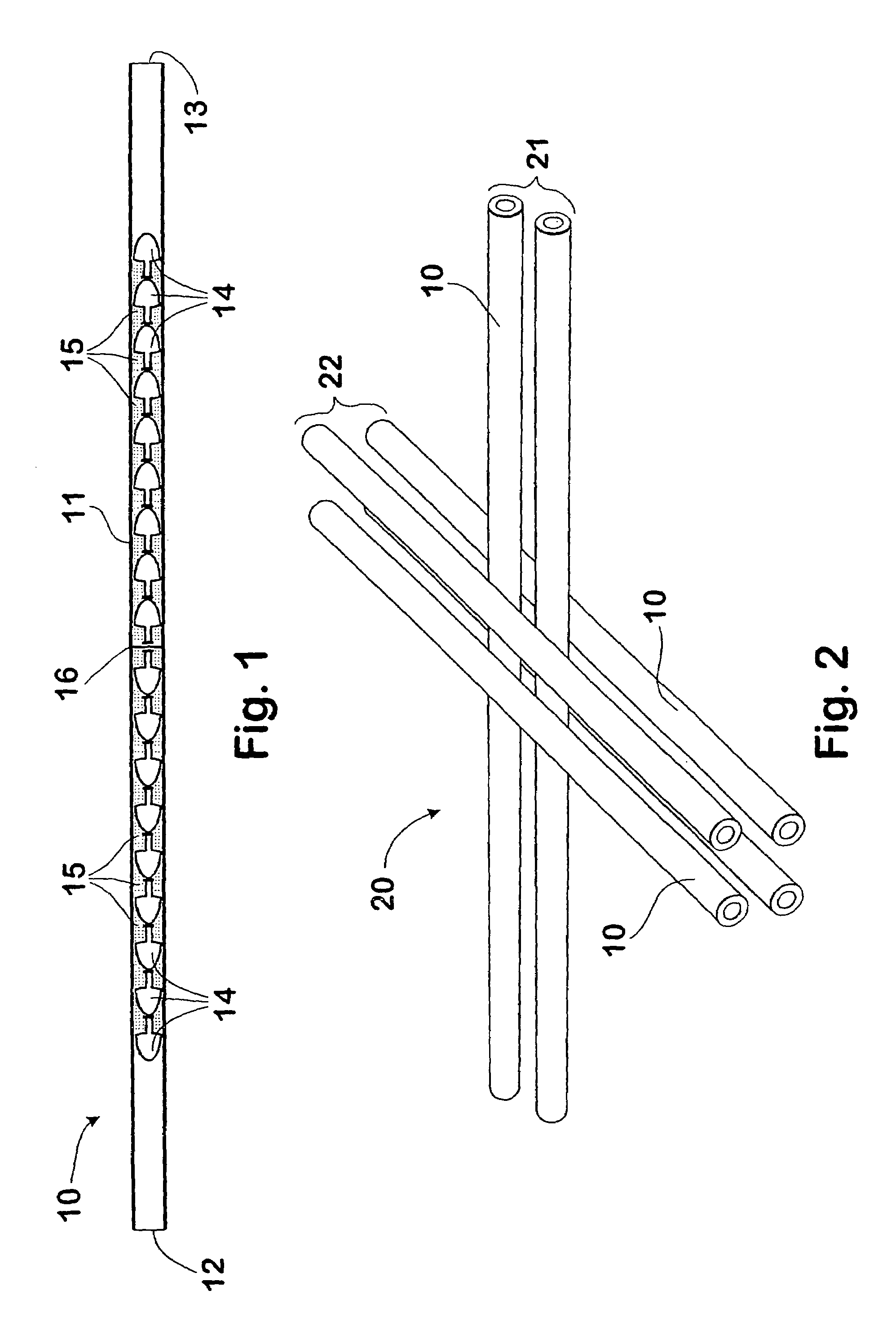
[0031]FIG. 1 shows a barrel assembly 10 including a barrel 11 having opposed muzzle ends 12, 13, wherein the barrel is loaded with a plurality of projectiles 14 and associated propellant charges 15. The barrel of the embodiment is formed from a lightweight carbon fibre based composite material. The barrel 11 has been loaded such that projectiles 14 are axially stacked in the barrel commencing from a common breech wall 16, whereby projectiles may be fired from either or both muzzle ends, as desired. The propellant 15 is arranged to be selectively ignited by electrical means (not shown) so that the projectiles may be sequentially fired at a selected rate of fire from the barrel 11. Desirably the arrangements for firing the projectiles are substantially in accordance with the teachings of earlier patent applications by the present inventor.

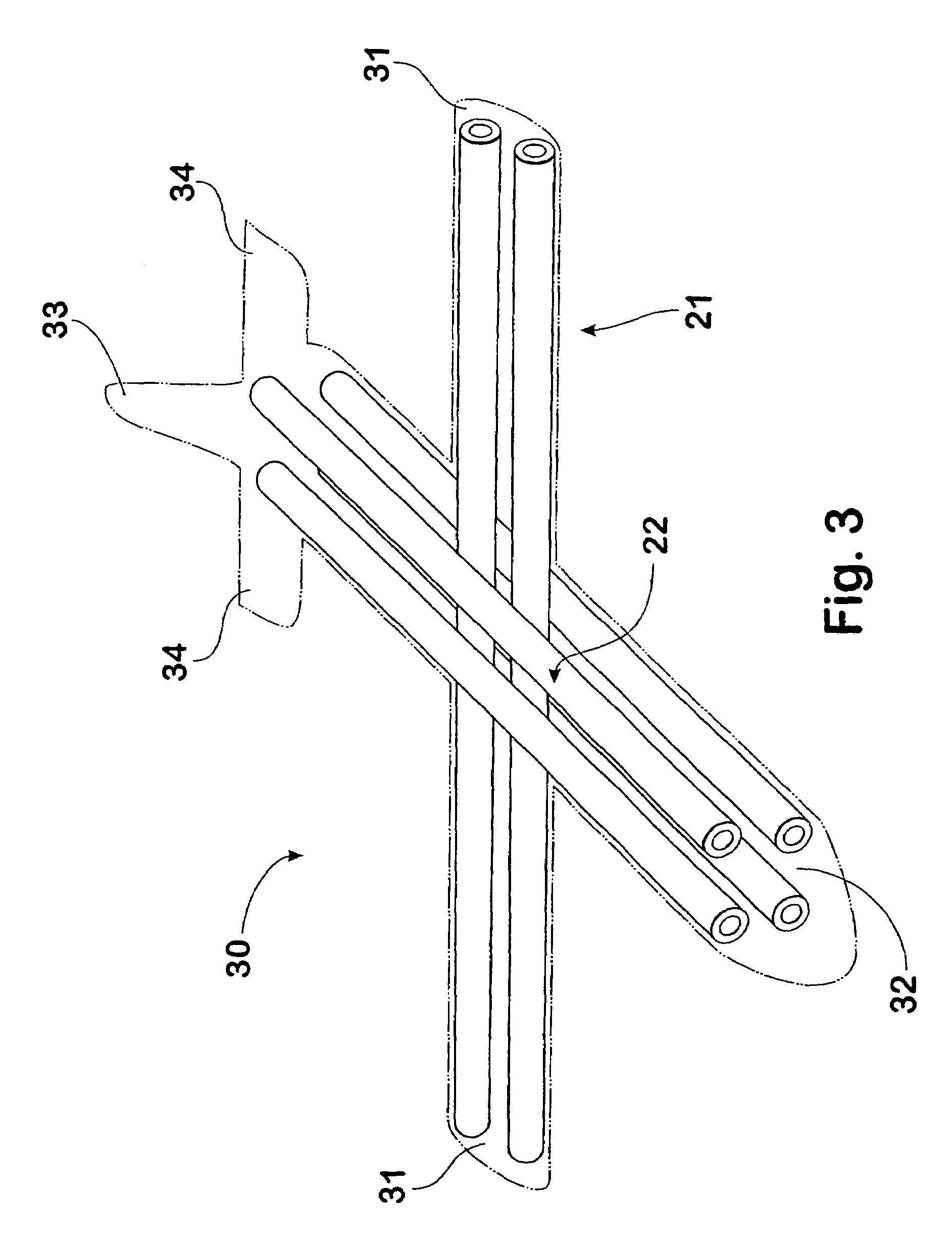
[0032]A structural frame 20 of a weapons platform is illustrated in FIG. 2, here formed from a plurality of the barrel assemblies 10 described in re...


PUM


Abstract

A vehicular weapons platform (30) including a plurality of barrel assemblies (10), wherein each barrel assembly includes a barrel (11), a plurality of projectiles (14) axially disposed within the barrel for operative sealing engagement with the bore of the barrel (11) and discrete propellant charges (15) for propelling respective projectiles sequentially through the muzzle of the barrel; and at least one of said plurality of barrel assemblies (10) includes a barrel which also forms a structural member of the weapons platform. In one preferred form, the weapons platform takes the form of a small combat aerial vehicle (SCAV) (30), wherein the barrel assemblies (10) form the airframe. A method of constructing a weapons platform from the barrel assemblies is also described.

Description

[0001]The present patent application is a non-provisional application of International Application No. PCT / AU02 / 01441, filed Oct. 24, 2002, which claims priority from Australian Application PR8801 / 01 filed Nov. 12, 2001, which is herein incorporated by reference.BACKGROUND OF THE INVENTION[0002]1. Field of the Invention[0003]This invention relates to vehicular weapons platforms and methods of construction thereof. The invention finds particular, but not exclusive application in relation to the construction of airborne vehicles.[0004]2. Discussion of the Background Art[0005]Weapons systems are typically fitted to existing vehicular platforms as separate and discrete components, albeit in many cases functionally integrated with other mechanical and electronic systems of the vehicle. The mass of weapons systems is often a key consideration in the design of mobile platforms together with allowance for dynamic effects of firing, such as recoil and changes to mass distribution as ammuniti...

Claims


Application Information

Patent Timeline
Patent Type & Authority Patents(United States)
IPC IPC(8): F41A23/02F41A9/72B63G1/00B64C39/02B64D7/00B64D7/04B64D7/08F41A21/08F41A21/20F41A21/36F41A21/48F41A23/00F42B5/03
CPCB64D7/00B64D7/04B64D7/08F41A21/48F41A23/00F42B5/035B64C2201/121B64U2101/18B64U2101/15
Inventor O'DWYER, JAMES MICHAEL
Owner DEFENDTEX
Why Eureka
Try Eureka