Image forming apparatus having a photosenstive member of high capacitance

a technology of capacitance and photoensing, applied in the field of image forming apparatus, can solve the problems of image defect, “deficit charging”, “blank area” and other problems, and achieve the effect of suppressing image defects

Active Publication Date: 2012-12-04
CANON KK
View PDF15 Cites 4 Cited by
  • Summary
  • Abstract
  • Description
  • Claims
  • Application Information

AI Technical Summary

Benefits of technology

[0041]An object of the present invention is to provide an image forming apparatus, capable of suppressing an image defect in case of utilizing a photosensitive member of a high capacitance.
[0042]Another object of the present invention is to provide an image forming apparatus capable of reducing an image blank area generated in a boundary portion between images of mutually different image densities.
[0043]Still another object of the present invention is to provide an mage image forming apparatus capable of suppressing, in a development, a deficient charging on the latent image potential by the toner.
[0044]Still another object of the present invention is to provide an mage image forming apparatus excellent in tone reproducibility.

Problems solved by technology

However, in order that the copying machine and the like can enter the printing market, an image quality, an output speed and a stability even higher than the current level are essential issues to be solved.
However, the amorphous silicon photoreceptor (hereinafter represented as α-Si photoreceptor) involves a drawback of causing an image defect, called “blank area”.
It is therefore liable to cause a “deficient charging” in which the charge potential cannot fully fill in the development contrast Vcont.
As explained above, an image bearing member of a high capacitance, such as an α-Si photoreceptor, involves a drawback of causing a blank area image defect by the deficient charging described above.
Now there will be explained a drawback in tone reproducibility caused by such deficient charging.
On the other hand, in an image bearing member of a high capacitance, the development of the latent image cannot be completed properly because of a deficient charging, whereby the developed toner amount increases.
A shift to a higher capacitance in the image bearing member is unavoidable in the trend hereafter toward a higher image quality and a higher stability.

Method used


Image

  • Image forming apparatus having a photosenstive member of high capacitance
  • Image forming apparatus having a photosenstive member of high capacitance
  • Image forming apparatus having a photosenstive member of high capacitance

Examples


embodiment 1

(5) Embodiment 1

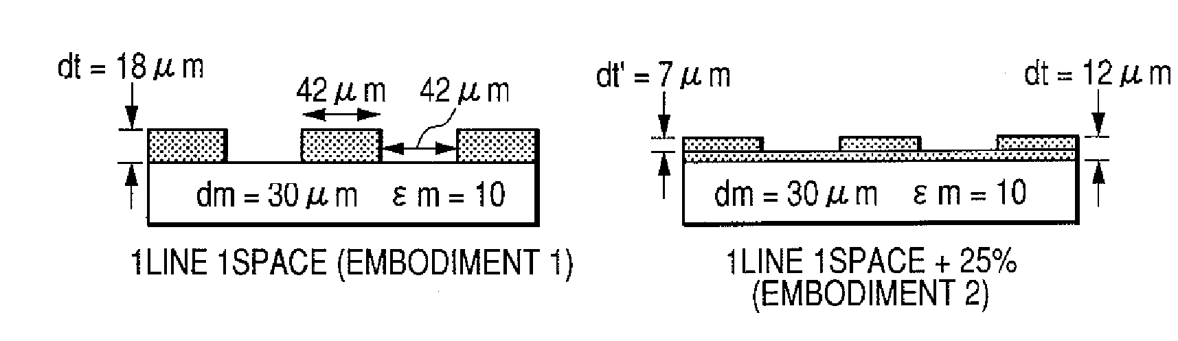
[0091]In this Embodiment 1, the development in a solid portion is executed on a latent image of an irregularity structure, obtained by a screen (line) process that has ordinarily been employed in a highlight portion and a medium tone portion. In such development, there is employed toner of a same amount as in the development of a solid portion in the conventional method. It is therefore featured in realizing, in a solid portion, an irregularity structure having a higher toner layer and including also an air layer in addition to the toner layer.

[0092]Results of the investigation will be explained. As the testing apparatus, there was employed a modified iRC-6800 apparatus, utilizing a digital image exposure process and a reversal developing process. The used image bearing members include an organic photoreceptor and an α-Si photoreceptor, explained below. The organic photoreceptor had a film thickness dm of 28 μm, a relative permittivity εm of 3.3, and a capacitance C / ...

embodiment 2

(6) Embodiment 2

[0116]In Embodiment 2, an investigation was made without a complete interspacing (thinning) in the Embodiment 1 of the toner image on the image bearing member. More specifically, in the solid portion employed in Embodiment 1 (line-space resolution of 600 dpi), the laser beam was so modulated as to execute an irradiation with a lowered intensity even in a portion corresponding to a white background portion formed by spaces. Thus a toner layer was formed even in a recessed portion in the irregularity structure of the toner layer. Results are shown in FIG. 19. It was confirmed that the toner layer on the image bearing member had an irregularity structure, without a complete interspacing (thinning). More specifically, toner is not formed in the recessed portion in Embodiment 1, while toner is formed in the recessed portion in Embodiment 2. A measured charging efficiency, a difference dt′ between a toner layer height in the recessed portion and a toner layer height in the...

embodiment 3

(7) Embodiment 3

[0123]In contrast to Embodiment 1 (utilizing a screen structure formed by lines), Embodiment 3 employed a screen structure, formed by dots, for the development in the solid portion. Other conditions were same as those in Embodiment 1. Table 9 shows results of comparison of a 2-dot-1-space process with the 2-line-1-space process in Embodiment 1, and comparison of a 3-dot-1-space process with the 3-line-1-space process in Embodiment 1. The 2-dot-1-space process is executed by turning on the laser beam continuously for 2 dots and then turning off for 1 dot in repetition along the main scanning direction of the photosensitive member, and the 3-dot-1-space process is executed by turning on the laser beam continuously for 3 dots and then turning off for 1 dot in repetition along the main scanning direction of the photosensitive member. Thus, the number of spaces in this case means a number of turn-offs of the laser beam in the main scanning direction. A number of spaces in...


PUM


Abstract

An image forming apparatus includes a photosensitive member, having a capacitance per unit area of 1.7×10⁻⁶ (F / m2) or larger, an exposure device, which exposes the photosensitive member in order to form thereon an electrostatic image according to image information, a developing device, which develops the electrostatic image with a toner to form a toner image on the photosensitive member, and a transfer device, which transfers the toner image onto a recording material. In forming a solid toner image on the recording material, the exposure device is capable of forming electrostatic images of different potential levels on the photosensitive member, thereby forming toner images of different toner heights on the photosensitive member.

Description

BACKGROUND OF THE INVENTION[0001]1. Field of the Invention[0002]The present invention relates to an image forming apparatus of electrophotographic process, such as a copying machine or a printer.[0003]It particularly relates to an image forming apparatus utilizing a photosensitive member of a high capacitance having a capacitance (C / S) per unit area satisfying a relation C / S≧1.7×10⁻⁶ (F / m2)[0004]2. Description of the Related Art[0005]In the image forming apparatus of electrophotographic process, a higher image quality, a higher output speed and a higher stability for the output image are being requested along with the advancement toward the full-color configuration and the digital structure, and an entry into the printing market is expected. However, in order that the copying machine and the like can enter the printing market, an image quality, an output speed and a stability even higher than the current level are essential issues to be solved.[0006]An image bearing member currently...

Claims


Application Information

Patent Timeline
Patent Type & Authority Patents(United States)
IPC IPC(8): G03G15/043
CPCG03G5/047G03G5/08214G03G5/08235G03G15/04072G03G15/326G03G2215/0404G03G2215/0495
Inventor KUBO, KENTAHARAGUCHI, MANAMIYAMAMOTO, TAKESHI
Owner CANON KK
Why Eureka
Try Eureka