
Image forming apparatus and cleaning control method

a technology of image forming apparatus and cleaning control method, which is applied in the direction of electrographic process apparatus, instruments, corona discharge, etc., can solve the problems of large amount of ozone to be generated, shorten the life of the photoreceptor, and uneven image appearance, so as to reduce the current value, suppress image defects, and reduce the amount of ozone

Active Publication Date: 2013-05-30
SHARP KK
View PDF2 Cites 4 Cited by
  • Summary
  • Abstract
  • Description
  • Claims
  • Application Information

AI Technical Summary

Benefits of technology

The present invention relates to an image forming apparatus and a cleaning control method that can suppress image defects such as image blurring and white spots. The invention aims to decrease the amount of ozone generated from the charging portion by preventing an excessive amount of ozone, which can lead to the formation of these image defects. Additionally, the invention provides a cleaning member that can clean the needle electrode of the charging portion by sequentially coming into contact with tip portions of saw teeth, and a control method for controlling the cleaning member to achieve stable image quality.

Problems solved by technology

However, there is a problem that ozone generated in corona discharge lowers resistance of the photoreceptor to cause image defects such as image blurring and white spots, thereby shortening a life of the photoreceptor.
Further, there is a problem that at the end of life, unevenness of an image appears since siloxane and the like are attached to tips of saw teeth.
In order to make unevenness of an image less visible, it is necessary to increase the saw-tooth current or increase applied voltage, thus causing a large amount of ozone to be generated.
Accordingly, there has been a problem in the related art that a saw-tooth current is increased in consideration of a charge life under initial conditions, thereby causing an excessive amount of ozone to be generated.

Method used


Image

  • Image forming apparatus and cleaning control method
  • Image forming apparatus and cleaning control method
  • Image forming apparatus and cleaning control method

Examples


example 1

[0108]Example 1 shows a saw-tooth current value when the initial saw-tooth current value C is regarded as 600 μA, and the coefficient β is regarded as −80.

[0109]The saw-tooth current value I1 is represented by the following formula (3).

Saw-tooth current value: I1=(Print cumulative count value D) X α+(600+(−80 X Number of operations for saw-tooth cleaning G)) μA  (3)

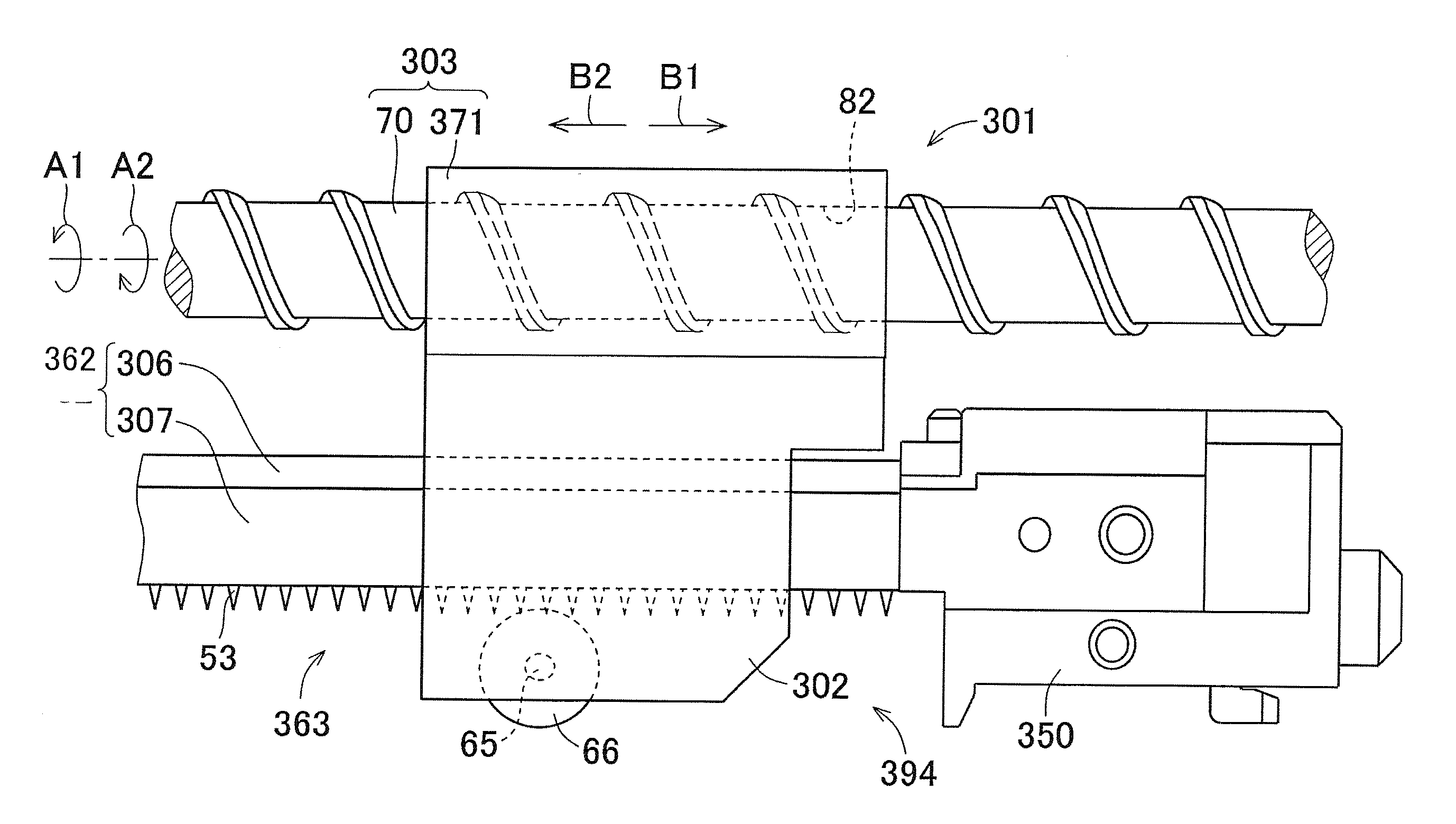
[0110]Next, description will be given based on a flowchart for motion control of the cleaning rubber roller 66 based on the print cumulative count by the control portion 202 in the charging device 301 of the present embodiment.

[0111]When motion control of the cleaning rubber roller 66 based on the print cumulative count according to the present invention is started, as shown in FIG. 11, print cumulative count value is confirmed by the control portion 202 in the image forming apparatus 100 (step S10), and determination is made whether or not the print cumulative count value reaches a saw-tooth cleaning count value (step S1...


PUM


Abstract

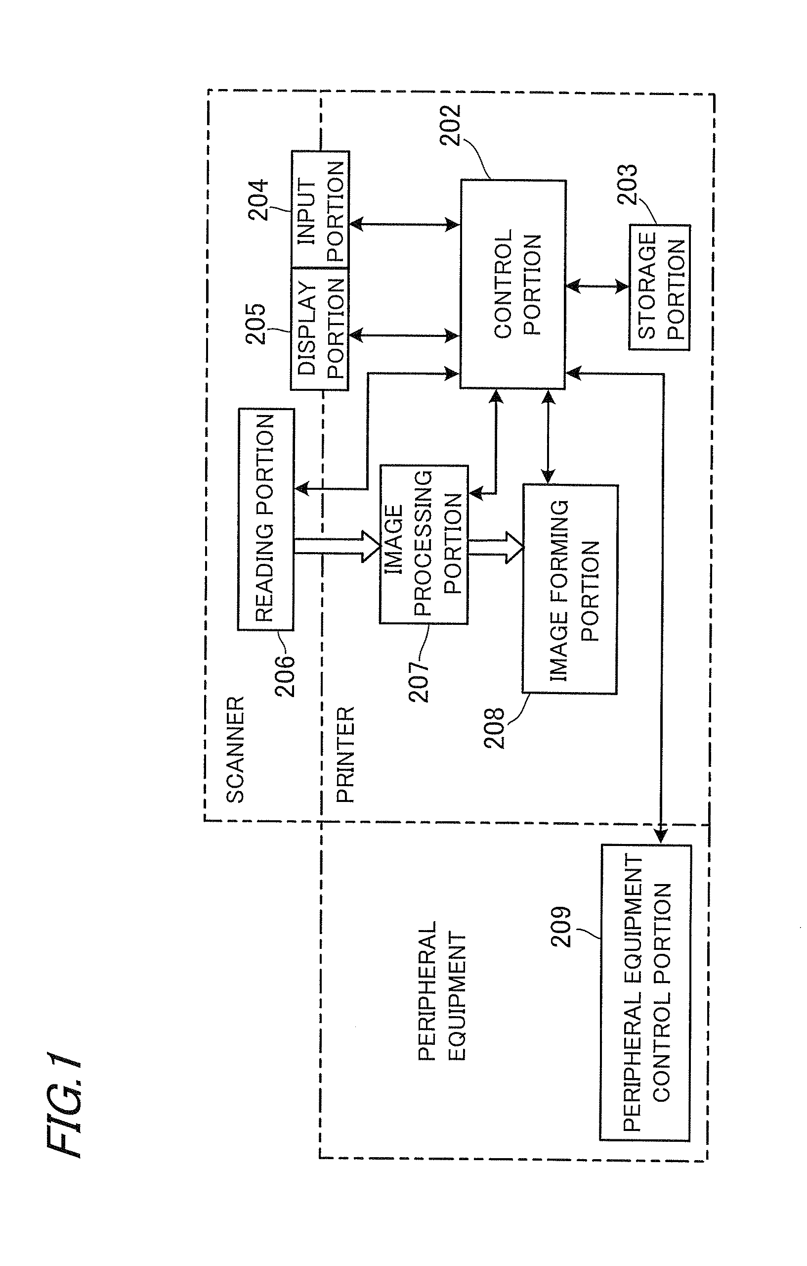
In an image forming apparatus for forming an image by electrophotography, a charging device is comprised of a needle electrode in which a plurality of saw teeth are arrayed in one direction; a cleaning rubber roller that cleans the needle electrode; a cleaning member supporter; a moving portion that moves the cleaning member supporter; and a control portion that controls the charging device, and the control portion includes a function to increase a saw-tooth current value by increasing print cumulative count; and a function to decrease the saw-tooth current value at the time of performing cleaning.

Description

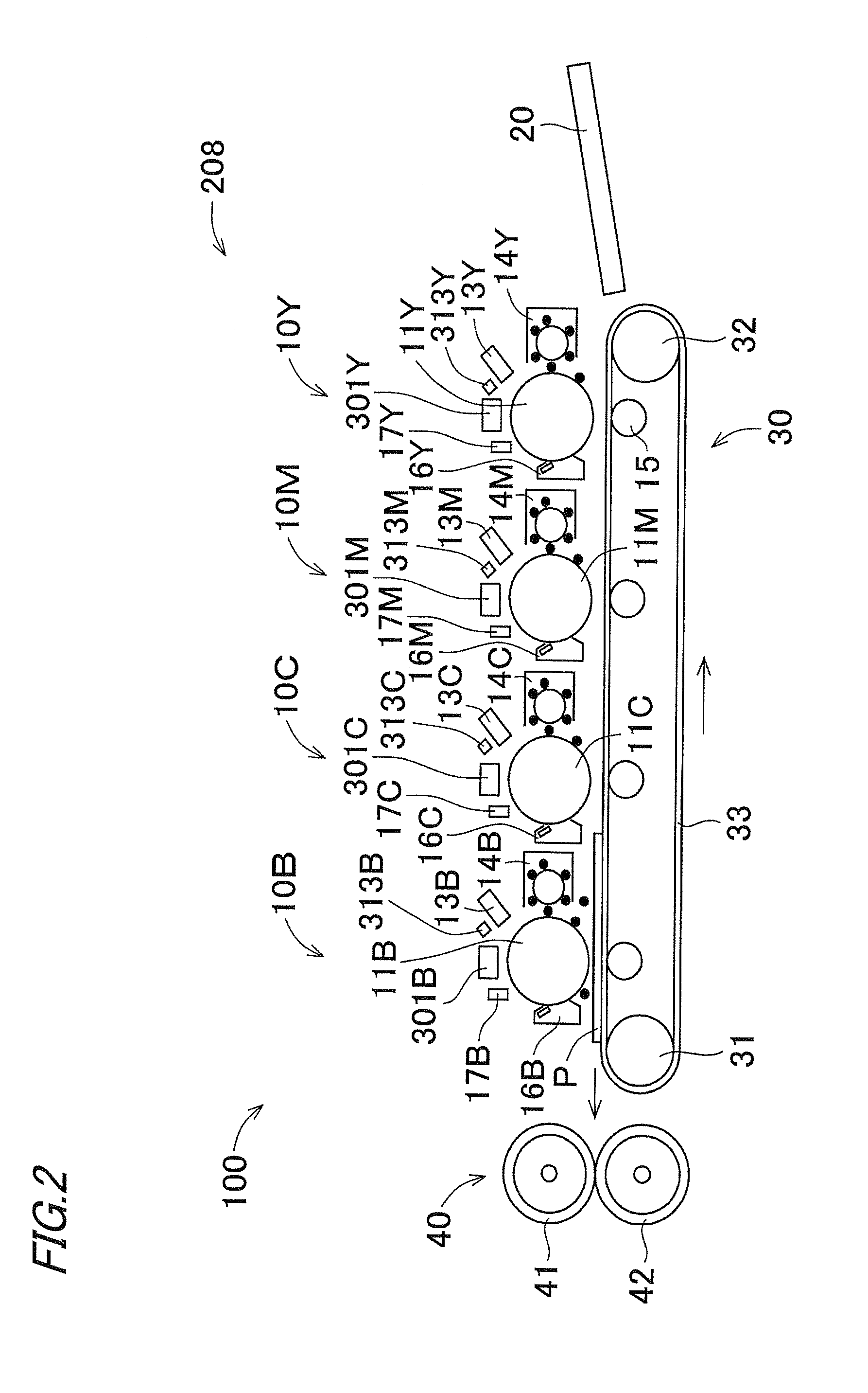
[0001]This Nonprovisional application claims priority under 35 U.S.C. §119(a) on Patent Application No. 2011-258951 filed in Japan on 28 Nov. 2011, the entire contents of which are hereby incorporated by reference.BACKGROUND OF THE INVENTION[0002](1) Field of the Invention[0003]The present invention relates to an image forming apparatus and a cleaning control method, and specifically to an image forming apparatus by electrophotography provided with a charging device for charging the surface of a photoreceptor to perform image formation based on an electrostatic latent image formed on the photoreceptor, and a cleaning control method.[0004](2) Description of the Prior Art[0005]An image forming apparatus by electrophotography is equipped with a charging device for uniformly charging the surface of a photoreceptor. The charging device includes, for example, a noncontact type charging device that does not come into contact with the surface of the photoreceptor. The noncontact type chargi...

Claims


Application Information

Patent Timeline
Patent Type & Authority Applications(United States)
IPC IPC(8): G03G15/02
CPCG03G15/0291G03G15/0225G03G15/0258G03G2215/028
Inventor YONEDA, IORITAKANO, KATSUYA
Owner SHARP KK
Learn More