
Image processing method and image processing apparatus, and image forming apparatus comprising image processing apparatus

a technology of image processing and image processing apparatus, which is applied in the direction of visual presentation, instruments, computing, etc., can solve the problems of affecting the image quality of the image, so as to achieve the effect of suppressing image defects

Inactive Publication Date: 2006-11-16
FUJIFILM CORP
View PDF5 Cites 3 Cited by
  • Summary
  • Abstract
  • Description
  • Claims
  • Application Information

AI Technical Summary

Benefits of technology

The present invention provides an image processing method, apparatus, and system for forming high-quality dots in an image by using a dot formation device. The method involves determining dot arrangement based on the characteristics of the dot formation device and the fixing characteristics of the recording medium. This allows for optimal dot formation even in cases where there are errors in the dot formation process. The method also includes comparing the dot arrangement data with a threshold value to reduce computational load and improve image processing efficiency. The invention aims to prevent image defects caused by the characteristics of the dot formation device and to achieve a suitable dot formation for different recording media.

Problems solved by technology

Although Japanese Patent Application Publication No. 6-245060 discloses an error diffusion method using a plurality of color printer models, it involves a possibility in that it may be difficult to achieve sufficient improvement in image quality, because it is based on circular dots and the great effects on image quality caused by dot position error or size error are not taken into account.
Furthermore, although the effects of the spreading of ink from the peripheral pixels are reflected in the error of the pixel under examination, the error diffused from the adjacent pixels, which is taken into account when the pixel under examination is quantized, includes the effects of ink spreading from adjacent pixels to the adjacent pixels, and the quantization error in the adjacent pixels.
However, the method described in Japanese Patent Application Publication No. 2002-240327 is not based on the effects of ink spreading from adjacent pixels into the pixels adjacent to the pixel under examination, and therefore, it is difficult that the effects of the projection of the ink droplets are reflected accurately in the pixel under examination.

Method used


Image

  • Image processing method and image processing apparatus, and image forming apparatus comprising image processing apparatus
  • Image processing method and image processing apparatus, and image forming apparatus comprising image processing apparatus
  • Image processing method and image processing apparatus, and image forming apparatus comprising image processing apparatus

Examples


first embodiment

[0125] Next, a method of forming dots in an image processing method according to the present invention will be described.

[0126]FIG. 8 shows a flowchart of a dot formation method in an information processing method according to a first embodiment. According to the present embodiment, halftoning process is carried out by determining the formation of dots at the dot formation positions according to a threshold value matrix with the use of the dot model described above, and thereby a high-quality image is obtained.

[0127] More specifically, in the dot formation method according to the present embodiment, in forming an image by forming dots on a recording medium, it is determined whether to form a dot at a position (x, y) on the recording medium or not, by comparing the image signal (which may be a density value) I(x, y) at that position (x, y) with a prescribed threshold value T(x, y), in accordance with a sequence (dot formation position sequence) for determining whether to form a dot ...

second embodiment

[0156] Next, a method of forming dots in an image processing method according to the present invention will be described.

[0157] In the second embodiment, dot formation is determined according to an error diffusion method on the basis of dot models such as those described above. In the present embodiment, the determination of dot formation is carried out in a raster sequence. Moreover, the determination of dot formation in the present embodiment is performed by comparing the result of the image density value I(x, y) at the dot formation position, minus the error E(x, y) and the effect XM(x, y) from the peripheral positions, with the threshold value T(x, y).

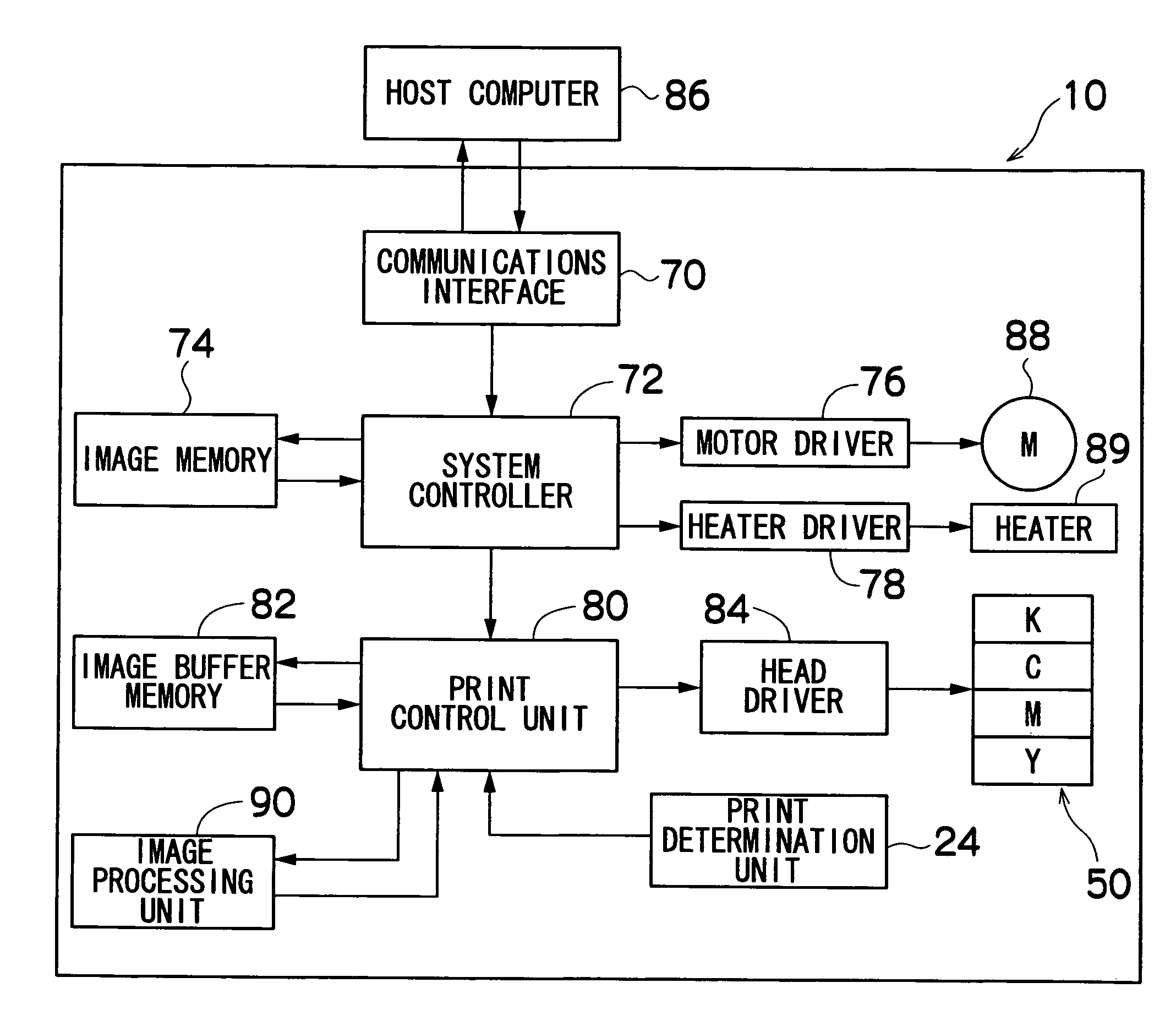
[0158]FIG. 9 is a block diagram showing the approximate composition of an image processing unit forming an image processing apparatus according to the second embodiment. As shown in FIG. 9, the composition of the image processing unit 190 according to the present embodiment is substantially the same as the composition of the image...

third embodiment

[0192]FIG. 15 is a flowchart showing the sequence of the processing of the dot formation method according to this

[0193] As shown in FIG. 15, the present embodiment is approximately the same as the second embodiment shown in FIG. 10. The steps whose last two digits of the step numbers in FIGS. 10 and 15 are the same, correspond to each other.

[0194] The difference of the present embodiment with respect to the second embodiment is that, in step S320, when the generated error Enew is calculated, the effects on the already quantized positions in the peripheral positions of the dot model M(x, y) are also treated as error, and this error is diffused to the unquantized pixels.

[0195] More specifically, in the case of the example shown in FIG. 11 and FIG. 12, the generated error Enew is calculated as shown in the following equation:

Enew=I(x,y)+E(x,y)+XM(x,y)−M(x,y;22)−M(x,y;11)−M(x,y;21)−M(x,y;31)−M(x,y;12).

[0196] For example, in the case of the example shown in FIG. 13 and FIG. 14, the g...


PUM


Abstract

An image processing method comprises the steps of: determining dot arrangement in forming an image with dots on a recording medium; and forming the image on the recording medium by means of a dot formation device according to the dot arrangement, wherein dot arrangement data concerning each of dot formation positions on the recording medium is created from input image data, according to a dot model which is established with respect to each of the dot formation positions, the dot model being determined according to at least one of dot formation characteristics of the dot formation device and fixing characteristics of the recording medium, and including information relating to at least one of a dot shape, dot density, a dot position, and presence or absence of a satellite, of each dot formed on the recording medium.

Description

BACKGROUND OF THE INVENTION [0001] 1. Field of the Invention [0002] The present invention relates to an image processing method, an image processing apparatus, and an image forming apparatus comprising an image processing apparatus, and more particularly, to half-toning technology based on the effects of various errors occurring when dots are actually formed by a printer. [0003] 2. Description of the Related Art [0004] An image forming apparatus, such as an inkjet printer, thermal printer, or LED printer, is known which forms images on a recording medium by means of dots. In an image forming apparatus of this kind, images are formed by means of a plurality of dots formed by liquid ink droplets, toner particles, or the like. Therefore, basically, an image is formed according to existence and nonexistence of dots on a recording medium such as white paper. Since the number of inks used is limited, a half-toning method is known which is used to achieve continuous tonal gradation by mean...

Claims


Application Information

Patent Timeline
Patent Type & Authority Applications(United States)
IPC IPC(8): B41J2/205
CPCG06K15/102H04N1/405H04N1/40031
Inventor YAMAZAKI, YOSHIROU
Owner FUJIFILM CORP
Learn More