

Image forming apparatus
An image forming equipment and equipment technology, applied in copiers or facsimile machines, and laser beam printers, can solve the problems of image defects, double images, increased agglomeration of toner particles, and reduced charge, etc.
- Summary
- Abstract
- Description
- Claims
- Application Information
AI Technical Summary
Problems solved by technology
Method used
Image

Examples
Embodiment 1
[0023] The image forming apparatus according to the present invention will be described in more detail below with reference to these drawings.
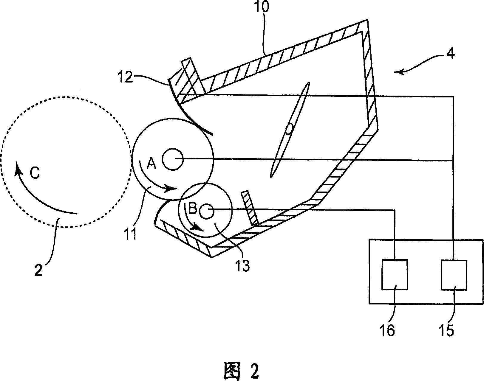
[0024] 1 is a schematic sectional view of an image forming apparatus according to the present invention, and FIG. 2 is a schematic sectional view of a developing device employed in the image forming apparatus.
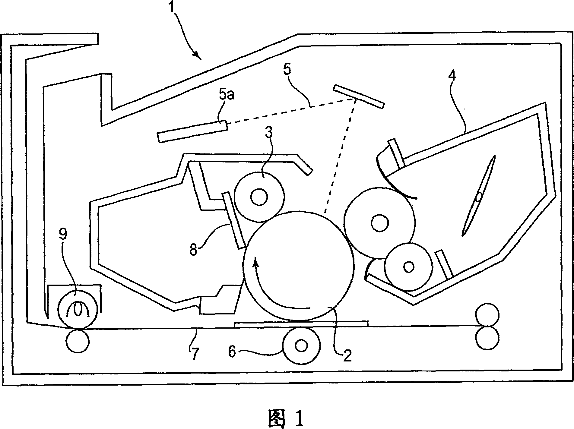
[0025] First, the general structure and operation of an image forming apparatus 1 constructed according to the present invention will be described with reference to FIG. 1 .
[0026] The image forming apparatus 1 in this embodiment is a laser beam printer that forms an image on a sheet of transfer medium (recording paper, OHP sheet, fabric, etc.) using an electrophotographic image forming method and outputs the sheet of recording medium. More specifically, it forms an image on a recording medium based on an image information signal from an image information source (such as a personal computer, a document reading device, etc.) ...
Embodiment 2
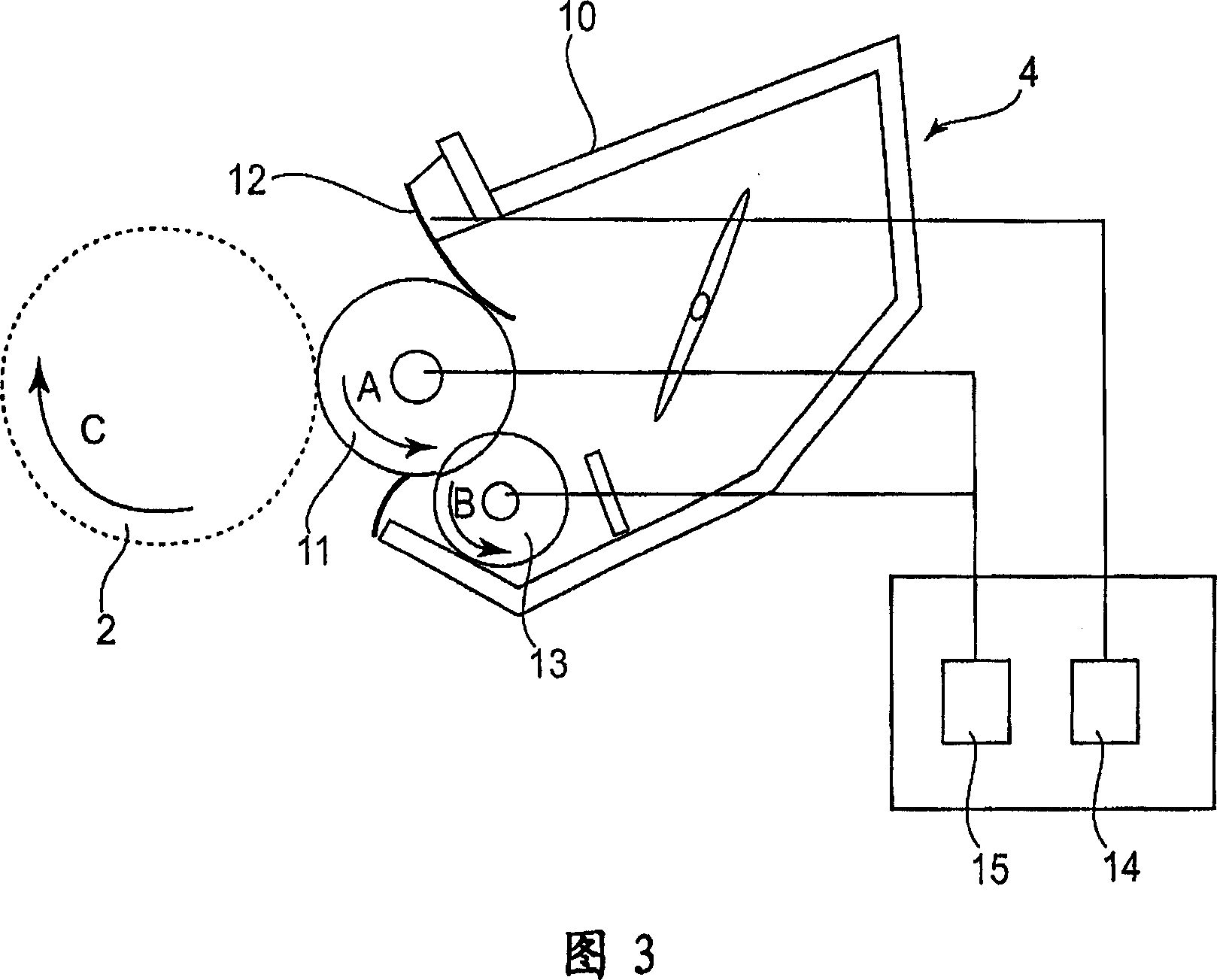
[0051] Hereinafter, referring to FIG. 3, a developing device employed in an image forming device in another preferred embodiment of the present invention will be described. The basic structure and operation of the developing device and image forming device in this embodiment are substantially the same as those in the first preferred embodiment. Therefore, elements of the device in this embodiment that actually have the same function and structure as those of the first embodiment or elements that are functional or structural equivalents thereof adopt the same reference numerals as those of the first embodiment, and do not Describe in detail. This embodiment differs from the first embodiment in that a roller whose arithmetic average roughness Ra (JIS B 0601-1994) satisfies the following mathematical expression is used as the developing roller 11, where Ra [μm] and X [μm ] represents the average roughness Ra of the developing roller and the volume average particle size of the de...
Embodiment 3
[0100] 4 is a schematic sectional view of an embodiment of a process cartridge 30 detachably mountable in an image forming apparatus according to the present invention.
[0101] The process cartridge 30 has a developing roller 11 as a developer carrying member, a toner blade 12 as a developer regulating member, a supply roller 13 and the like. The regulating blade 12 is disposed such that one of its major surfaces is in contact with the peripheral surface of the developing roller 11 . The developing device 4 in this embodiment has the same structure as that in the first embodiment. The process cartridge 30 includes a developing device 4, a photosensitive drum 2, a charging device 3, and a cleaning blade 8 as a cleaning device, which are integrally provided in a plastic supporting member, a part of which constitutes a waste toner storage part.
[0102] In other words, the process cartridge 30 in this embodiment is an assembly of the above-described developing device 4 and a un...
PUM
| Property | Measurement | Unit |
|---|---|---|
| Depth | aaaaa | aaaaa |
| Average surface roughness | aaaaa | aaaaa |
| Volume average particle size | aaaaa | aaaaa |
Abstract
Description
Claims
Application Information