Image forming apparatus

a technology of forming apparatus and forming roller, which is applied in the direction of electrographic process apparatus, instruments, optics, etc., can solve the problems of reducing the contact opportunity, reducing the degree of deterioration of toner, and deterioration of both photosensitive drums and developing rollers. , to achieve the effect of reducing contact opportunities, reducing costs, and simplifying the constitution

Active Publication Date: 2016-08-11
CANON KK
View PDF3 Cites 4 Cited by
  • Summary
  • Abstract
  • Description
  • Claims
  • Application Information

AI Technical Summary

Benefits of technology

[0010]A principal object of the present invention is to provide an image forming apparatus capable of realizing simplification of a constitution and a reduction in cost by commonality of driving means for image bearing members and capable of reducing a contact opportunity between an image bearing member and a developing member while suppressing image defects.

Problems solved by technology

In the image forming apparatus employing the contact development type, there arises a problem that deterioration of both of the photosensitive drum and the developing roller due to abrasion (wearing) of the photosensitive drum and the developing roller is liable to generate.
In the contact development type, the photosensitive drum and the developing roller contact a toner, so that compared with a non-contact development type, a physical stress exerted on the toner is large and therefore there is a problem that a degree of deterioration of the toner is liable to increase.
However, the conventional constitutions involves the following problems.
However, in the case of single image formation or in the case where there is no need to increase the sheet interval even when the images are continuously formed, an effect of reducing a contact opportunity between the photosensitive drum and the developing roller cannot be obtained.
As a result, a fluctuation in peripheral speed of the objective photosensitive drum generates and disturbs the latent image to be formed in some cases.
However, there is a need to prepare the plurality of driving means, and therefore the constitution of the image forming apparatus is complicated, and leads to an increase in cost.

Method used


Image

  • Image forming apparatus
  • Image forming apparatus
  • Image forming apparatus

Examples


embodiment 1

1. Structure of Image Forming Apparatus

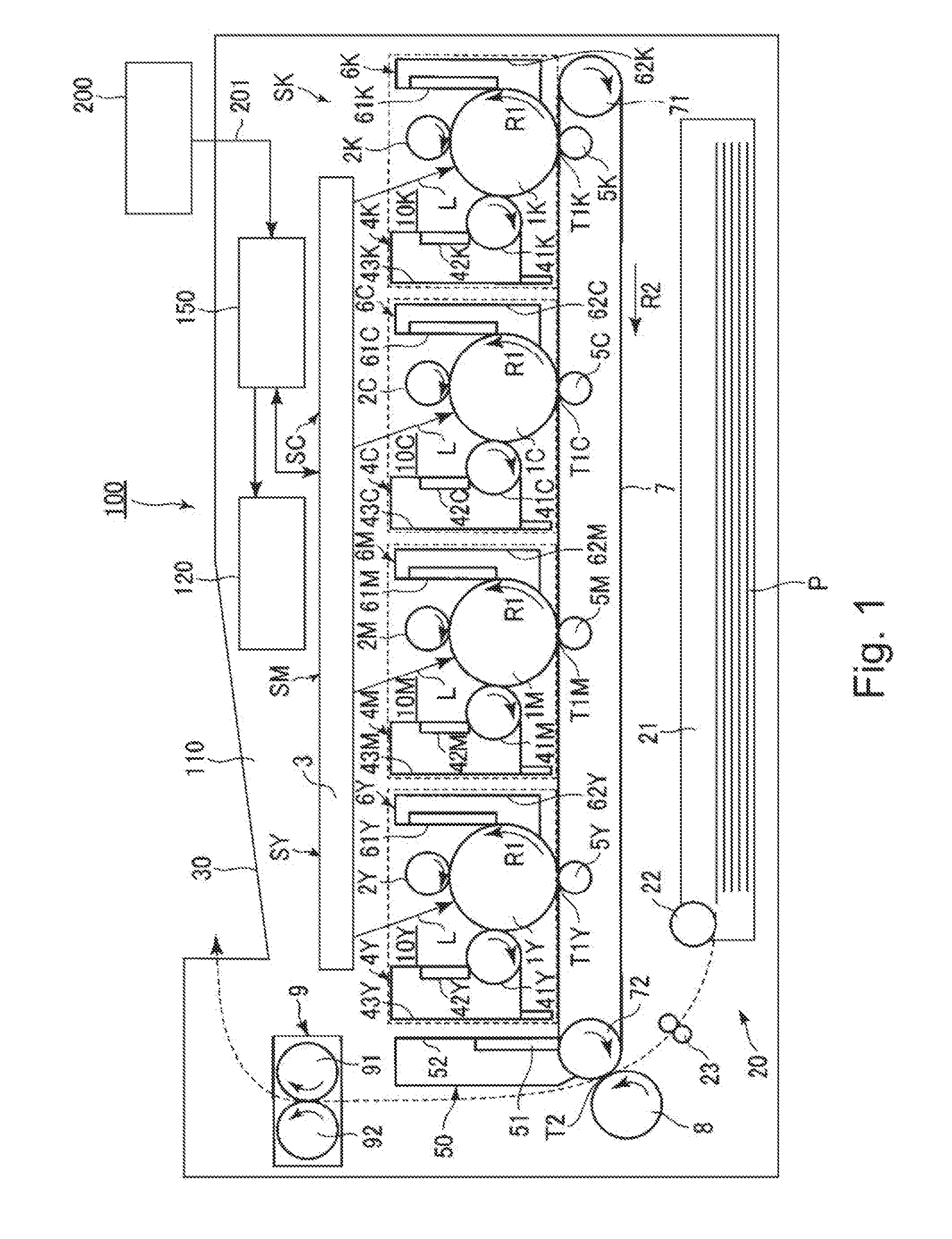
[0022]FIG. 1 is a schematic sectional view of an image forming apparatus 100 according to an embodiment of the present invention. In this embodiment, the image forming apparatus 100 is a tandem type color laser printer employing an intermediary transfer type in which first to fourth image forming portions (stations) SY, SM, SC, SK are provided. Image formation at the image forming portions SY, SM, SC, SK is effected using an electrophotographic process. At the image forming portions SY, SM, SC, SK, images of colors of yellow (Y), magenta (M), cyan (C), black (K) are formed, respectively.

[0023]Incidentally, with respect to elements which are provided at the image forming portions SY, SM, SC, SK and which have the same functions and structures, in the case where the elements are not required to be particularly distinguished, suffixes Y, M, C, K of reference numerals or symbols showing the elements for any of the image forming portions are omitted...

embodiment 2

[0068]Another embodiment of the present invention will be described. Basic constitution and operation of an image forming apparatus in this embodiment are the same as those in Embodiment 1. Accordingly, elements having the same or corresponding functions or constitutions as those for the image forming apparatus in Embodiment 1 are represented by the same reference numerals or symbols, and will be omitted from detailed description.

[0069]In Embodiment 1, the constitution in which all of the photosensitive drums 1Y, 1M, 1C, 1K were rotationally driven by the single drum driving motor 120 and the developing rollers 41Y, 41M, 41C, 41K were rotationally driven by the separate developing (roller) driving motors was employed.

[0070]On the other hand, in this embodiment, a constitution in which all of the photosensitive drums 1Y, 1M, 1C, 1K are all of the developing rollers 41Y, 41M, 41C, 41K are rotationally driven by the single driving motor 120 is employed.

[0071]Further, in this embodiment...

embodiment 3

[0075]Another embodiment of the present invention will be described. Basic constitution and operation of an image forming apparatus in this embodiment are the same as those in Embodiments 1 and 2. Accordingly, elements having the same or corresponding functions or constitutions as those for the image forming apparatus in Embodiments 1 and 2 are represented by the same reference numerals or symbols, and will be omitted from detailed description.

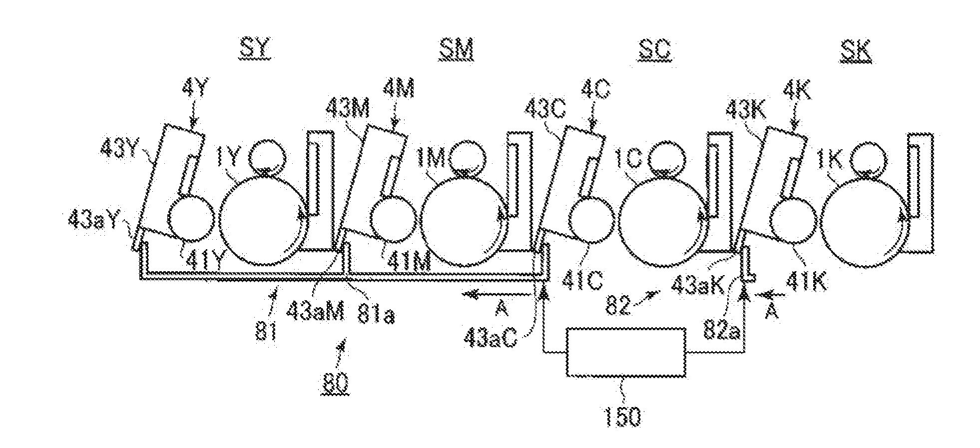
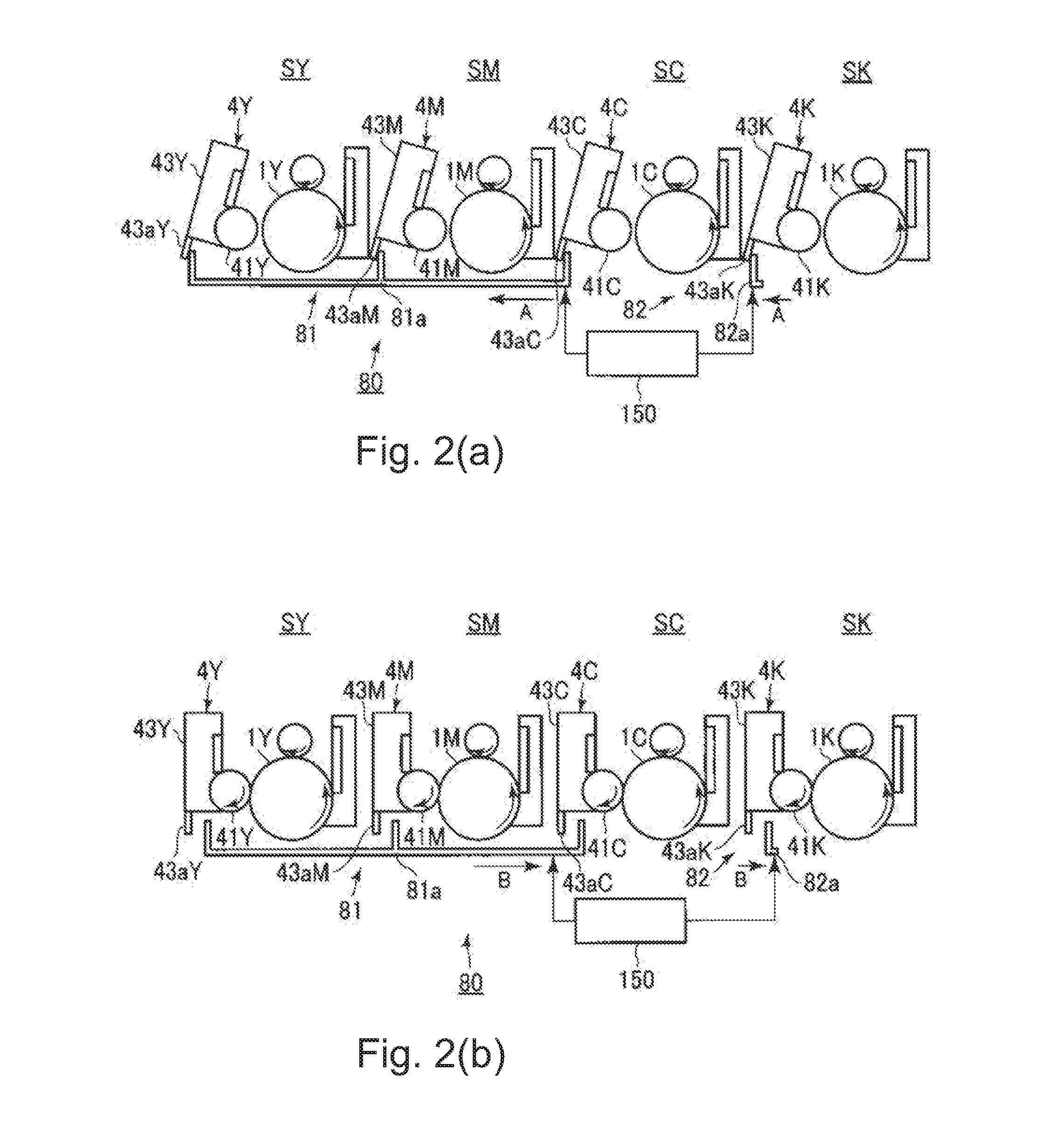
[0076]In this embodiment, the constitution in which the controller 150 sends the spacing signal to the YMC contact-and-separation mechanism 81 after the end of the latent image formation on the K photosensitive drum 1K and before the end of the transfer from the K photosensitive drum 1K was employed. After receiving the spacing signal, the YMC contact-and-separation mechanism 81 moves in the arrow A direction in (a) of FIG. 2, so that the YMC developing rollers 41Y, 41M, 41C are spaced from the YMC photosensitive drums 1Y, 1M, 1C. For that rea...


PUM


Abstract

An image forming apparatus includes image bearing members, a latent image forming portion, developing units each including a developing member, a movable member, a common driving source, a contact-and-separation unit, and a control unit. The image forming apparatus is capable of forming the images in an operation in an image forming mode. After end of the latent image formation on one of the image bearing members on which latent image formation is finally started and before end of transfer of an associated image from the one image bearing member, the control unit outputs a spacing signal for spacing associated developing members from the other image bearing members, during the image formation in the operation in the mode.

Description

FIELD OF THE INVENTION AND RELATED ART[0001]The present invention relates to an image forming apparatus, such as a copying machine, a printer or a facsimile machine, using an electrophotographic process or an electrostatic recording process.[0002]Conventionally, for example, as a latent image developing type of an image forming apparatus, such as the copying machine, the printer or the facsimile machine, using the electrophotographic process, a contact development type image forming apparatus development is effected in a contact state between an image bearing member and a developing member is used. Description will be made using a photosensitive drum as the image bearing member and using a developing roller as the developing member.[0003]In the image forming apparatus employing the contact development type, there arises a problem that deterioration of both of the photosensitive drum and the developing roller due to abrasion (wearing) of the photosensitive drum and the developing rol...

Claims


Application Information

Patent Timeline
Patent Type & Authority Applications(United States)
IPC IPC(8): G03G15/08
CPCG03G21/1676G03G21/1647G03G21/1825G03G2215/0141G03G15/0121
Inventor KITAMURA, TAKUYA
Owner CANON KK
Why Eureka
Try Eureka