
Power node with network switch

Active Publication Date: 2012-12-18
SIGNIFY HLDG BV
View PDF50 Cites 46 Cited by
  • Summary
  • Abstract
  • Description
  • Claims
  • Application Information

AI Technical Summary

Problems solved by technology

While modern power strips may include overload protection and / or surge protection, they do not generally include signal and power electronics enabling the power strip to be incorporated into a networked energy management system.

Method used


Image

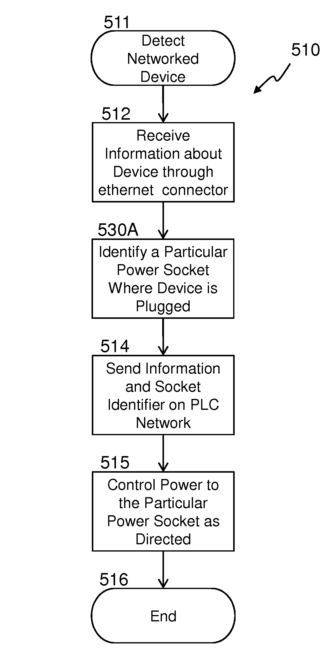
  • Power node with network switch
  • Power node with network switch
  • Power node with network switch

Examples


Embodiment Construction

[0023]In the following detailed description, numerous specific details are set forth by way of examples in order to provide a thorough understanding of the relevant teachings. However, it should be apparent to those skilled in the art that the present teachings may be practiced without such details. In other instances, well known methods, procedures and components have been described at a relatively high-level, without detail, in order to avoid unnecessarily obscuring aspects of the present concepts. A number of descriptive terms and phrases are used in describing the various embodiments of this disclosure. These descriptive terms and phrases are used to convey a generally agreed upon meaning to those skilled in the art unless a different definition is given in this specification. Reference now is made in detail to the examples illustrated in the accompanying drawings and discussed below.

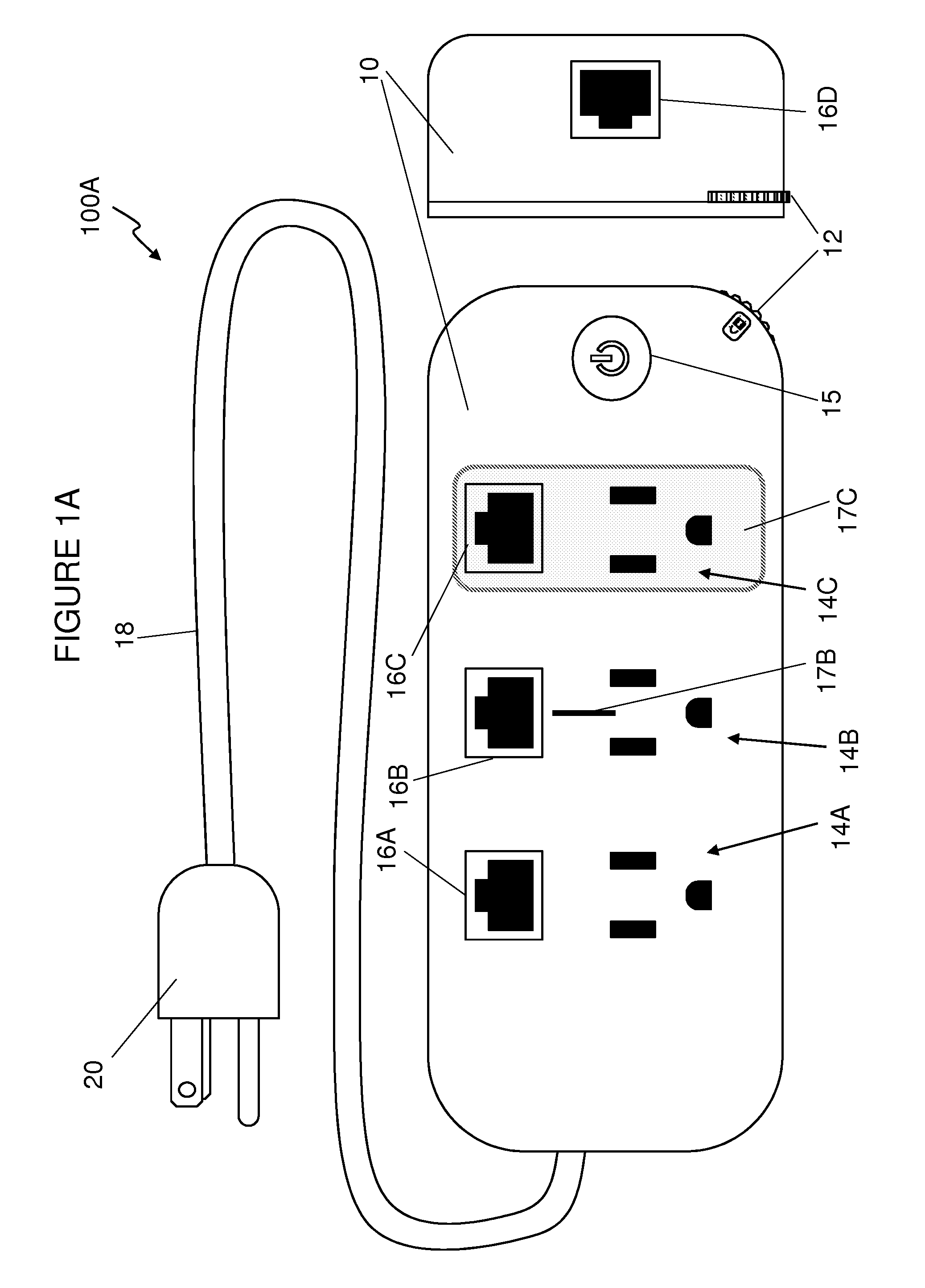
[0024]FIG. 1A shows an embodiment of a power node 100A. A power node housing or enclosure 10 inc...


PUM

PropertyMeasurementUnit
operational poweraaaaaaaaaa
threshold poweraaaaaaaaaa

Abstract

A power node provides energy management and network expansion features in a networked data communications and control environment that may be utilized in an energy management system implementing a method of managing energy. Network expansion may be provided by integrating a networking bridge from a power line network to one or more wired network ports or a wireless network. The power outlet on the power node providing power to a device may be identified and associated with information about the device.

Description

CROSS-REFERENCE TO RELATED APPLICATIONS[0001]This application is a continuation of International Patent Application No. PCT / US11 / 025350 filed on Feb. 18, 2011, which is a continuation-in-part of U.S. patent application Ser. No. 12 / 777,229 filed on May 10, 2010 and is a continuation-in-part of International Patent Application No. PCT / US10 / 053625 filed on Oct. 21, 2010, the entire contents of which are all hereby incorporated by reference.BACKGROUND[0002]1. Technical Field[0003]The present invention relates to an electrical power controller. In particular, a power node that also provides networking functionality.[0004]2. Description of Related Art[0005]Electric power strips typically have a plurality of electrical outlets mounted within an enclosure and an attached power cord for electrically interconnecting the outlets with an AC power source. While modern power strips may include overload protection and / or surge protection, they do not generally include signal and power electronics ...

Claims


Application Information

Patent Timeline
Patent Type & Authority Patents(United States)
IPC IPC(8): G06F1/26H02J3/14
CPCG01D4/002H01R13/703H01R25/003H02J3/14H02J13/0062H05B33/0848H01R13/6683Y04S40/124H02J2003/143Y02B70/3225Y02B70/3266Y02B90/245Y02B90/241Y02B90/226Y02B90/2638Y04S20/16Y04S20/222Y04S20/242Y04S20/32Y04S20/38Y04S20/40H05B45/14H02J2310/14H02J13/00002H02J2310/70H02J2310/16H02J13/00016H02J13/00004H02J13/0005Y02B70/30Y02B90/20Y04S20/00Y04S20/246G01D2204/24G01D2204/14H02J2310/66Y02A30/60Y04S20/30
Inventor JONSSON, KARLDIEHL, WILLIAMLYONS, TIMOTHYMANNICHE, MARTINWINDSTRUP, SONNY
Owner SIGNIFY HLDG BV
Learn More