Electro-mechanical firearm trigger mechanism

a trigger mechanism and electronic technology, applied in the field of electronic mechanical trigger mechanisms, can solve the problems of affecting the control and accuracy of the firearm, excessive firing rate in automatic firing mode, and high fire ra

Active Publication Date: 2012-12-25
COLT CANADA IP HLDG PARTNERSHIP
View PDF21 Cites 30 Cited by
  • Summary
  • Abstract
  • Description
  • Claims
  • Application Information

AI Technical Summary

Problems solved by technology

It is known that firearms that have purely mechanical automatic trigger mechanisms, such as the type disclosed in U.S. Pat. No. 3,045,555 to Stoner, can operate with excessively high firing rates in an automatic firing mode.
These high rates of fire may be problematic, as they can, among other things, affect the control and accuracy of the firearm, increase the accumulation of heat in the barrel, or result in unnecessary wastage of ammunition.
High rates of fire affect the control and accuracy of the firearm due to muzzle climb, as there is insufficient time between consecutive discharges to allow the operator to return the firearm to its original point of aim.
This is compounded by a desire to increase the portability and maneuverability of firearms by reducing weight and size, which respectively contribute to decreased stability and further increased rates of fire.
In addition, the accumulation of heat in the barrel may contribute to erosion and wear in the barrel, and can further impact the accuracy of the firearm.

Method used


Image

  • Electro-mechanical firearm trigger mechanism
  • Electro-mechanical firearm trigger mechanism
  • Electro-mechanical firearm trigger mechanism

Examples


Embodiment Construction

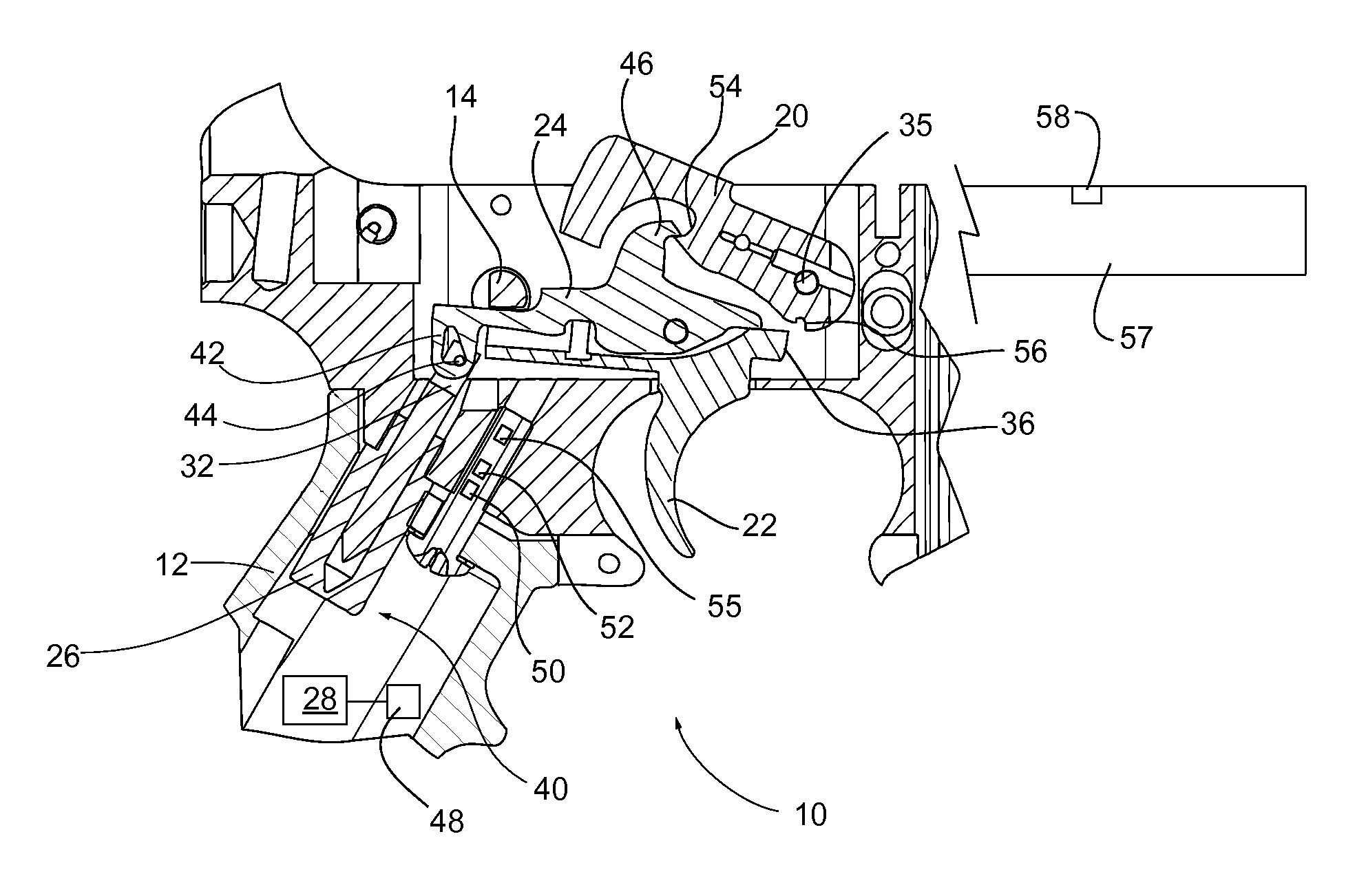
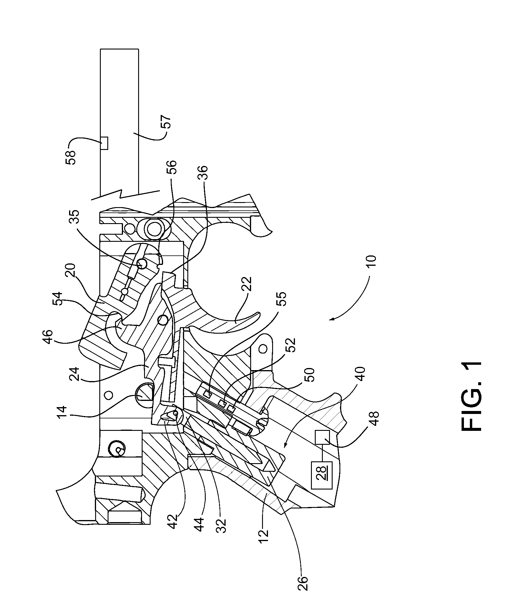
[0012]In this disclosure, an embodiment of an electro-mechanical trigger mechanism and a method for using such a mechanism to control a firearm are disclosed. Embodiments of the invention may be applied to a wide variety of firearms, but is shown here in an embodiment with an automatic firearm, such as an AR-15, M16 or U.S. Pat. No. 3,045,555 (Stoner) type.

[0013]FIG. 1 shows a first cross sectional view of a firearm 10 incorporating an electro-mechanical trigger mechanism. In one embodiment the electro-mechanical trigger mechanism 40 resides within a hand grip 12.

[0014]The electro-mechanical trigger mechanism 40 comprises a solenoid 26 which is in communication with, and controlled by, a processor 28, such as a central processing unit (CPU) and is also connected to a hammer 20 and a trigger 22 via a sear disconnect 24.

[0015]A firing mode selector 14 provides an apparatus for switching operation of the firearm 10 between a safe mode, a semi-automatic mode, and an automatic mode as de...


PUM


Abstract

An electro-mechanical firearm trigger mechanism for controlling the rate of fire for a firearm in automatic firing mode. The controlling being achieved through the use of a solenoid directed by a computer processor. The computer processor being connected to multiple sensors to instruct the solenoid on a rate of fire or to disengage automatic fire if needed.

Description

FIELD OF THE INVENTION[0001]Embodiments of the invention relate generally to firearms. More particularly, embodiments of the invention relate to an electro-mechanical trigger mechanism for an automatic firearm.BACKGROUND OF THE INVENTION[0002]It is known that firearms that have purely mechanical automatic trigger mechanisms, such as the type disclosed in U.S. Pat. No. 3,045,555 to Stoner, can operate with excessively high firing rates in an automatic firing mode. M16 type firearms using purely mechanical automatic trigger mechanisms can have rates of fire well in excess of 600 rounds per minute, particularly in models with shorter barrels. These high rates of fire may be problematic, as they can, among other things, affect the control and accuracy of the firearm, increase the accumulation of heat in the barrel, or result in unnecessary wastage of ammunition.[0003]High rates of fire affect the control and accuracy of the firearm due to muzzle climb, as there is insufficient time betw...

Claims


Application Information

Patent Timeline
Patent Type & Authority Patents(United States)
IPC IPC(8): F41A19/59
CPCF41A19/59F41A19/66
Inventor COMPTON, DAVID WALTERTEED, BRENTON STEWART
Owner COLT CANADA IP HLDG PARTNERSHIP
Why Eureka
Try Eureka