Fence post

a fence post and post technology, applied in fencing, building types, construction, etc., can solve the problems of inability to manufacture identical finished posts, inconvenient installation, and inability to fit horizontally, so as to achieve convenient installation

Active Publication Date: 2012-12-25
PRIEFERT MFG
View PDF20 Cites 15 Cited by
  • Summary
  • Abstract
  • Description
  • Claims
  • Application Information

AI Technical Summary

Benefits of technology

[0005]The present invention consists of a fence post that has a shaped hole for supporting fence rails over a wide range of angles to accommodate uneven terrain and curving sections of fencing. In a preferred embodiment, the posts are formed with perforating holes that have a central, smaller diameter section and a pair of flanking, larger diameter sections. The posts support fence rails that can take an angle to accommodate both uneven terrain and curving sections of the fence. The ends of the rails are preferably supported at one end on the smaller diameter section and the larger diameter flanking sections will help to mask any off-center position of the rail in the post. The invention also convenient to install because the posts can be set in the ground first and then the rails can be fed into the posts without having to start from one end of the whole fence in that a rail can be inserted at each post.

Problems solved by technology

If, however the terrain of the fence is not level, the rails will not be horizontal and will not fit within the horizontal, closely formed holes in the post.
The same problem exists if the fence is curving.
This prevented the manufacture of identical finished posts and required the installer to custom drill many of the posts.
The problem with this approach is that the rails rest on the bottom of the oversized holes and give an off-center look to the hole and the rail.

Method used


Image

  • Fence post
  • Fence post
  • Fence post

Examples


Embodiment Construction

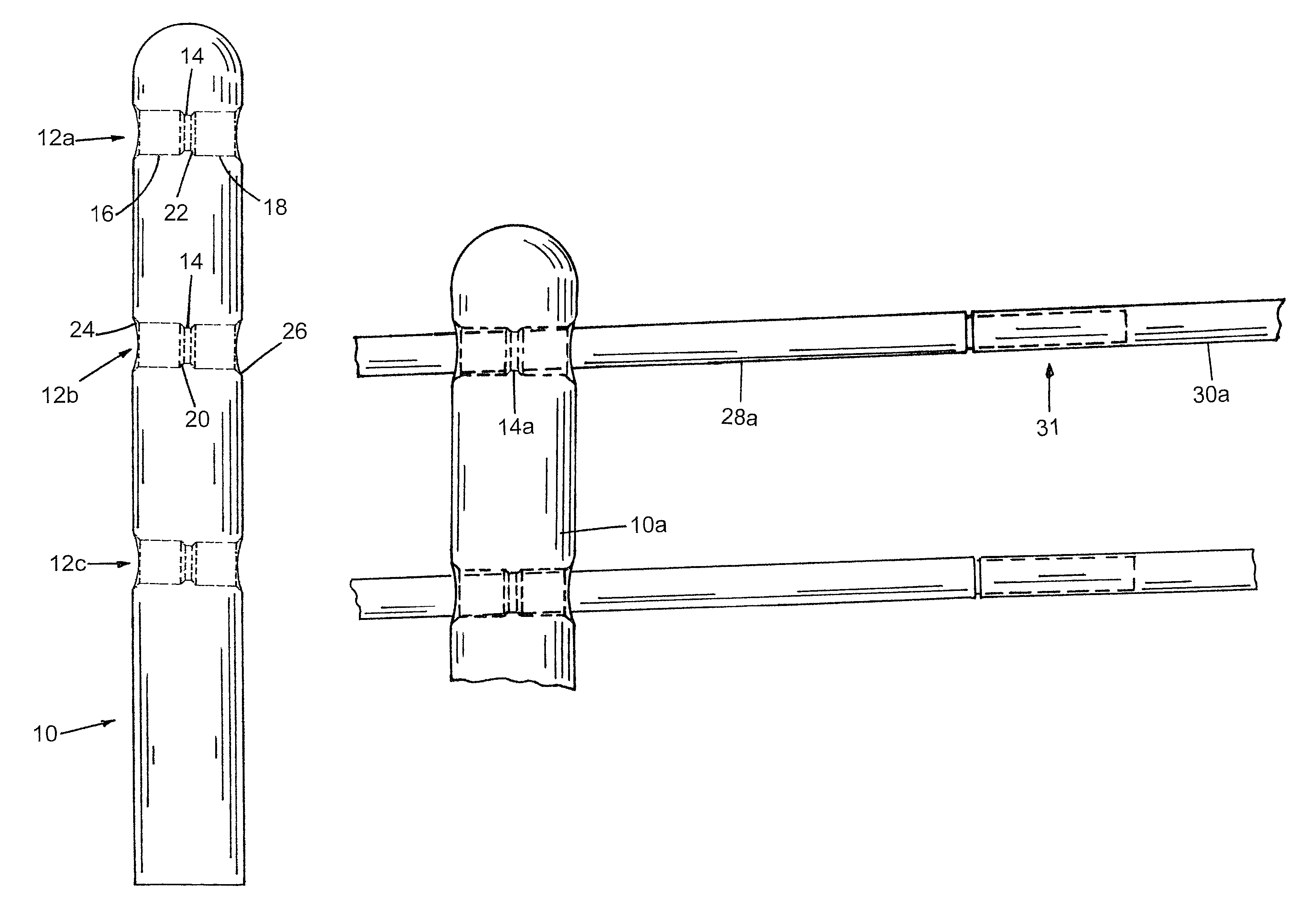
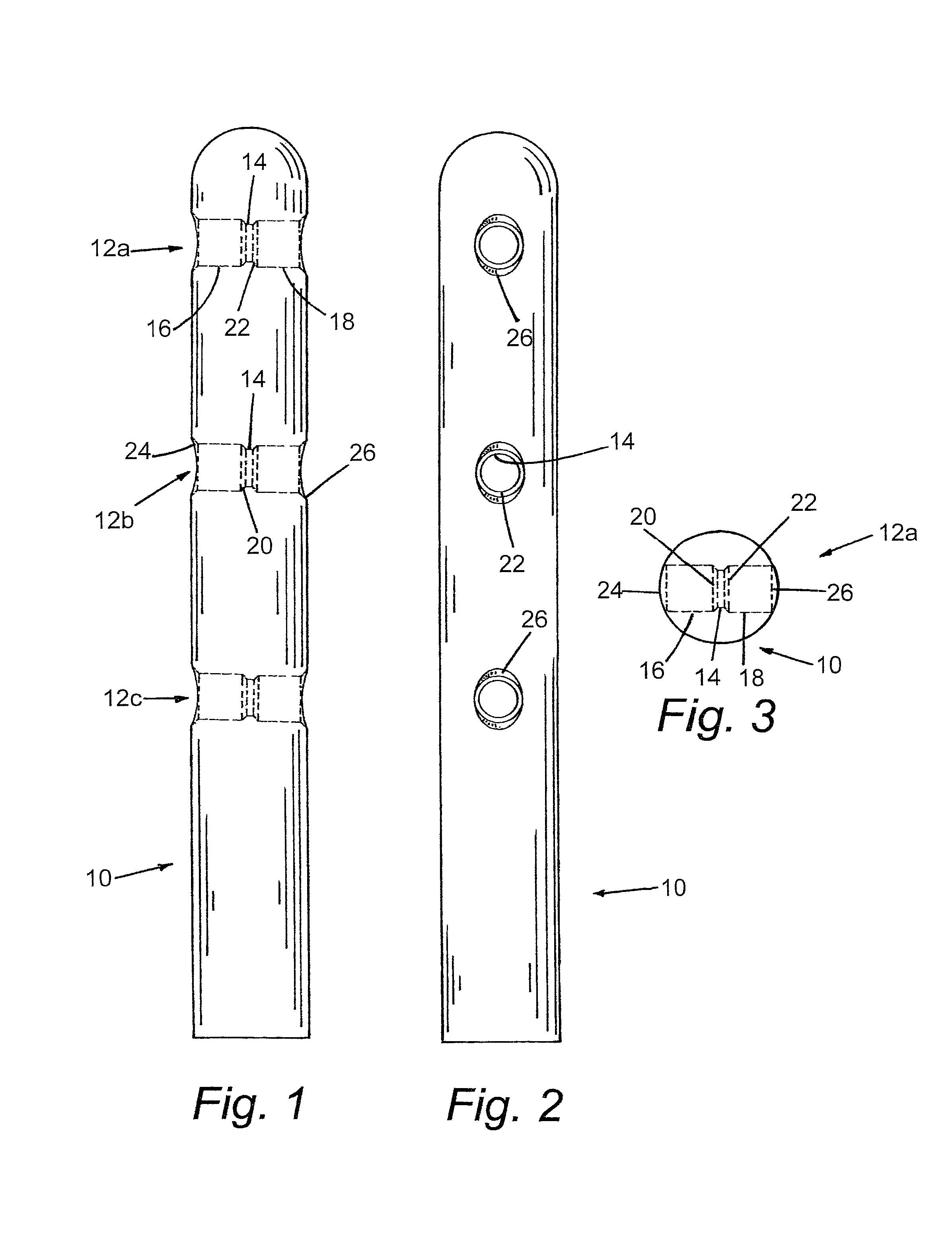
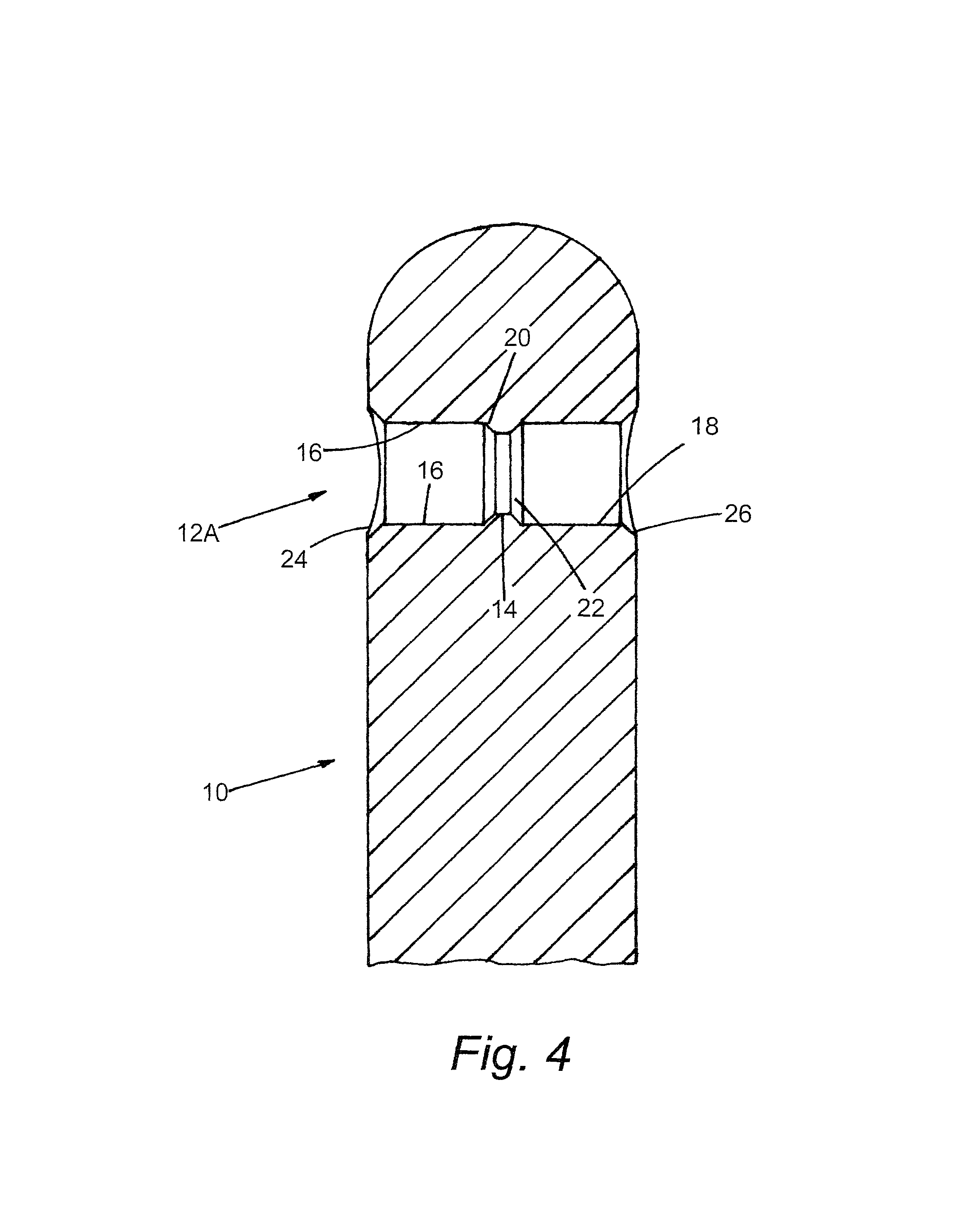
[0015]Illustrated in FIGS. 1-4, generally at 10, is a post representing a preferred embodiment of the present invention. The post 10 has three perforating holes 12a, 12b, and 12c. Each of the holes 12 includes a central section 14 having a smaller, first diameter, a first flanking section 16 of a larger, second diameter and a second flanking section 18 also of a larger, second diameter. In the preferred embodiment of the post 10, a first inner beveled section 20 transitions between the central section 14 and the flanking section 16 and a second inner beveled section 22 transitions between the central section 14 and the flanking section 18. Also in the preferred embodiment of the post 10, a first outer beveled section 24 flares outwardly from the flanking section 16 and a second outer beveled section 26 flares outwardly from the flanking section 18.

[0016]As illustrated in FIGS. 5-7, a plurality offence rails 28 and 30 may be supported by the posts 10. Each rail 28 has a first end of ...


PUM

PropertyMeasurementUnit
sizeaaaaaaaaaa
lengthaaaaaaaaaa
diameteraaaaaaaaaa

Abstract

A fence post for use in building a post and rail fence over varying terrain or of varying curvature. The post is perforated by a hole having a reduced diameter center section that is flanked on either side by an enlarged diameter section. The posts thus permit the support of rails that are not restricted to a straight, horizontal orientation and provide and improved overall appearance.

Description

[0001]This application claims priority to U.S. Patent Application Ser. No. 61 / 059,895, filed on Jun. 9, 2008.BACKGROUND OF THE INVENTION[0002]The present invention relates generally to fence posts and, more specifically, to fence posts in which have been formed shaped holes for supporting a tubular fence rail.[0003]Fences are in common use for defining property boundaries, for the containment of animals, for decorative purposes, and so on. While fences take on a wide plurality of forms, a common type of fence is comprised of a plurality of spaced-apart, ground supported posts and a plurality of fence rails supported on the posts and which form a barrier. The posts are plumb and typically all of a common height. The rails are supported in holes formed in the posts, with a first end of a rail supported in a first post and the second end of the rail supported in an adjacent, second post. If the terrain is level and the fence section is straight, the rails are horizontal and the holes a...

Claims


Application Information

Patent Timeline
Patent Type & Authority Patents(United States)
IPC IPC(8): E04H17/20
CPCE04H17/1421E04H17/20Y10T29/49826E04H2017/1465E04H17/1465E04H17/1417E04H17/1448
Inventor PRIEFERT, WILLIAM DEANCHRISTENBERRY, ROCKYDONNELLY, KELLY
Owner PRIEFERT MFG
Why Eureka
Try Eureka