
Hybrid arrow insert

a technology of inserting and arrows, applied in the field of inserting for archery arrows, can solve the problems of negative impact on the accuracy of arrows, inconsistent arrow flight, and nearly impossible to ensure concentric alignment of arrow points

Active Publication Date: 2012-12-25
HUANG DORGE OSOME
View PDF6 Cites 26 Cited by
  • Summary
  • Abstract
  • Description
  • Claims
  • Application Information

AI Technical Summary

Benefits of technology

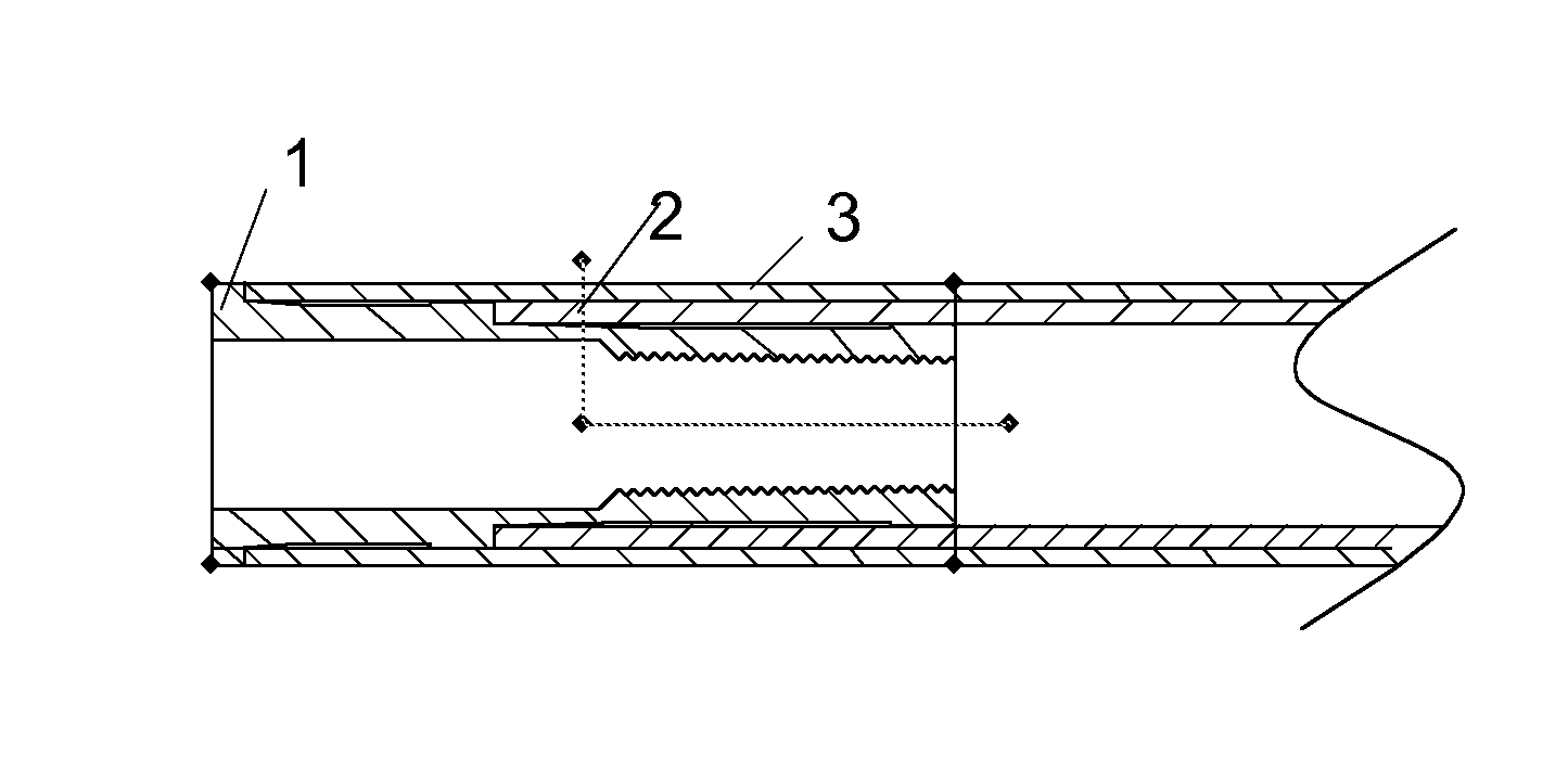
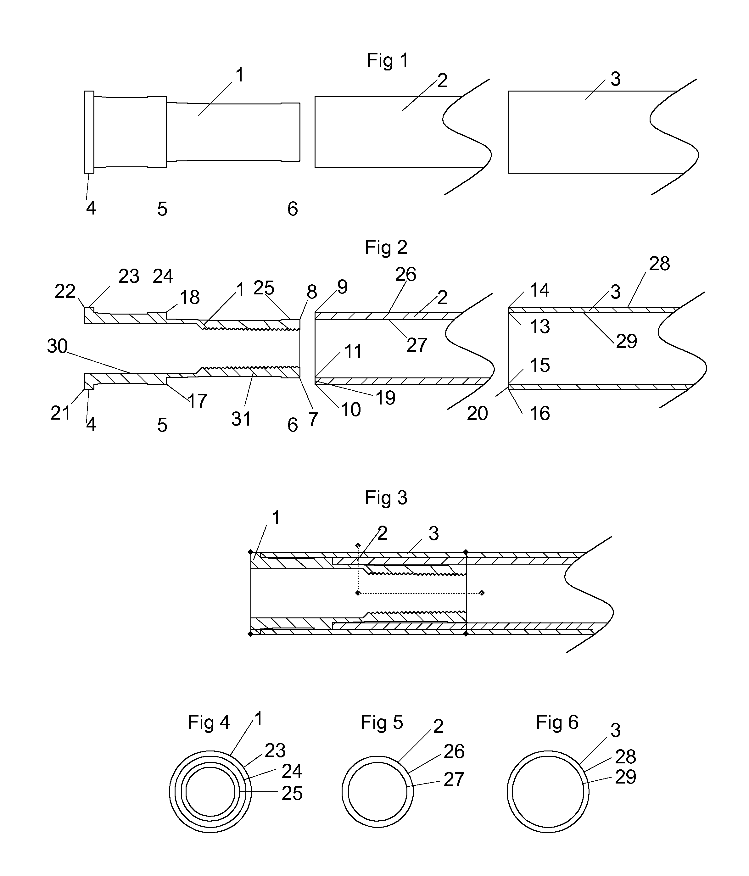
[0012]A dual step insert includes a head portion, a front neck portion, and a rear neck portion. An extension shaft is a tube shaped portion that includes an outside diameter, an inside diameter, and a wall thickness. An arrow shaft is a tube shaped structure that includes an outside diameter, an inside diameter, and a wall thickness. The dual step insert has a head portion diameter that is consistent with the outside diameter of the arrow shaft. The front neck portion diameter of the dual step insert is consistent with the outside diameter of the extension shaft. The rear neck portion diameter of the dual step insert is a diameter that is smaller than the inside diameter of the extension shaft. An outside rear neck portion of the dual step insert is used as an adhesive surface to adhesively couple the rear neck portion inside the front end of the extension shaft. Coupling of the dual step insert and the extension shaft create a hybrid arrow insert. The outside surface of the front neck portion and the outside surface of the extension shaft are now the adhesive surface for the hybrid arrow insert, which is adhesively coupled into the arrow shaft.

Problems solved by technology

New materials with greater strength, lighter weight projectiles, and aerodynamic vanes have all helped to increase performance, but there has always been an issue with dynamic forces on the arrow itself, and the consistent alignment of the arrow tip.
A short, single piece insert that was not concentrically aligned negatively impacted the accuracy of the arrow.
If the tolerances were poor on the insert or the shaft wall, it was nearly impossible to ensure concentric alignment of the arrow point, and consistent arrow flight.
In addition to poor flight characteristics, the short insert, due to its length, has very little adhesive surface area.
Having such a small adhesive surface, upon impact, it was common for the insert to come dislodged from the arrow shaft, thus forcing the insert and arrow tip rearward into the arrow shaft, causing the forward end of the arrow shaft to mushroom.
A problem with high powered bows has been the weakness of the spine of an arrow shaft.
One cure for this was to increase the wall thickness of the entire arrow shaft, but this added unwanted and unneeded weight to the arrow, thus decreasing performance.

Method used


Image

  • Hybrid arrow insert
  • Hybrid arrow insert

Examples


Embodiment Construction

[0019]FIG. 1 and FIG. 2 are views of the components of a hybrid arrow insert of the present invention. A dual step insert 1 includes a head portion 4, a front neck portion 5, and a rear neck portion 6. The dual step insert 1 is preferably fabricated from a metallic material. An extension shaft 2 is a tube shaped portion that has an outside diameter, an inside diameter, and a wall thickness. The extension shaft 2 is preferably fabricated from a nonmetallic material. An arrow shaft 3 is a tube shaped structure that has an outside diameter, an inside diameter, and a wall thickness. For clarity as relates to dimensions of the dual step insert 1, arrow shaft 3 and the extension shaft 2, FIG. 2, FIG. 4, FIG. 5, and FIG. 6 are used. The extension shaft outside diameter dimension 26 is the vertical distance when measured from intersection point 9 to intersection point 10; the extension shaft inside diameter dimension 27 is the vertical distance when measured from intersection point 11 to in...


PUM


Abstract

A dual step insert includes a head portion, a front neck portion, and a rear neck portion. An extension shaft is a tube shaped portion that includes an outside diameter, an inside diameter, and a wall thickness. An arrow shaft is a tube shaped structure that includes an outside diameter, an inside diameter, and a wall thickness. An outside rear neck portion of the dual step insert is used as an adhesive surface to adhesively couple the rear neck portion inside the front end of the extension shaft. Coupling of the dual step insert and the extension shaft create a dual step insert. The outside surface of the front neck portion and the outside surface of the extension shaft are now the adhesive surface for the dual step insert, which is adhesively coupled into the arrow shaft.

Description

BACKGROUND OF THE INVENTION[0001]1. Field of the Invention[0002]The present invention relates generally to archery arrows and more specifically to an insert for an archery arrow.[0003]2. Discussion of the Prior Art[0004]Historically there have been many advancements in the art of archery. From the earliest time when man first affixed a flint point to the end of a slender stick, and propelled it form a bow, he has strived to increase the performance and accuracy of the arrow. New materials with greater strength, lighter weight projectiles, and aerodynamic vanes have all helped to increase performance, but there has always been an issue with dynamic forces on the arrow itself, and the consistent alignment of the arrow tip.[0005]The present invention takes arrow performance to an all new level, by concentrically aligning the arrow insert, and strengthening the arrow shaft itself.[0006]Prior art of an arrow insert has been good at best, where the neck of the point and the threads might ...

Claims


Application Information

Patent Timeline
Patent Type & Authority Patents(United States)
IPC IPC(8): F42B6/04F42B6/08
CPCF42B6/04F42B6/08
Inventor HUANG, DORGE O'SOME
Owner HUANG DORGE OSOME
Learn More