Graphic display meter

a technology of display meter and display screen, which is applied in the direction of static indicating device, instruments, transportation and packaging, etc., can solve the problems of difficulty encountered, inconvenient vehicle users, and switch to motion blur display mod

Active Publication Date: 2012-12-25
YAZAKI CORP
View PDF6 Cites 7 Cited by
  • Summary
  • Abstract
  • Description
  • Claims
  • Application Information

AI Technical Summary

Problems solved by technology

In conventional graphic display meters, in a case where the pointer is driven to rotate rapidly, too many images of the pointer including its after-images are displayed thereon, causing inconvenience to a vehicle user.
However, a difficulty is encountered when the motion blur display mode is switched to the normal display mode.
The pointer is still moving at a speed ranging between the stopped state and the afore-mentioned high speed, resulting in a gap in dependence on the moving speed difference of the pointer between the normal display mode and the motion blur display mode.
As a result, at the time of the afore-mentioned mode changes, the vehicle operator recognizes both the motion blur pointer image and the normal pointer image at the same time, and also recognizes a space between the normal pointer image and the motion blur pointer image, which causes inconvenience to the vehicle operator.

Method used


Image

  • Graphic display meter
  • Graphic display meter
  • Graphic display meter

Examples


first embodiment

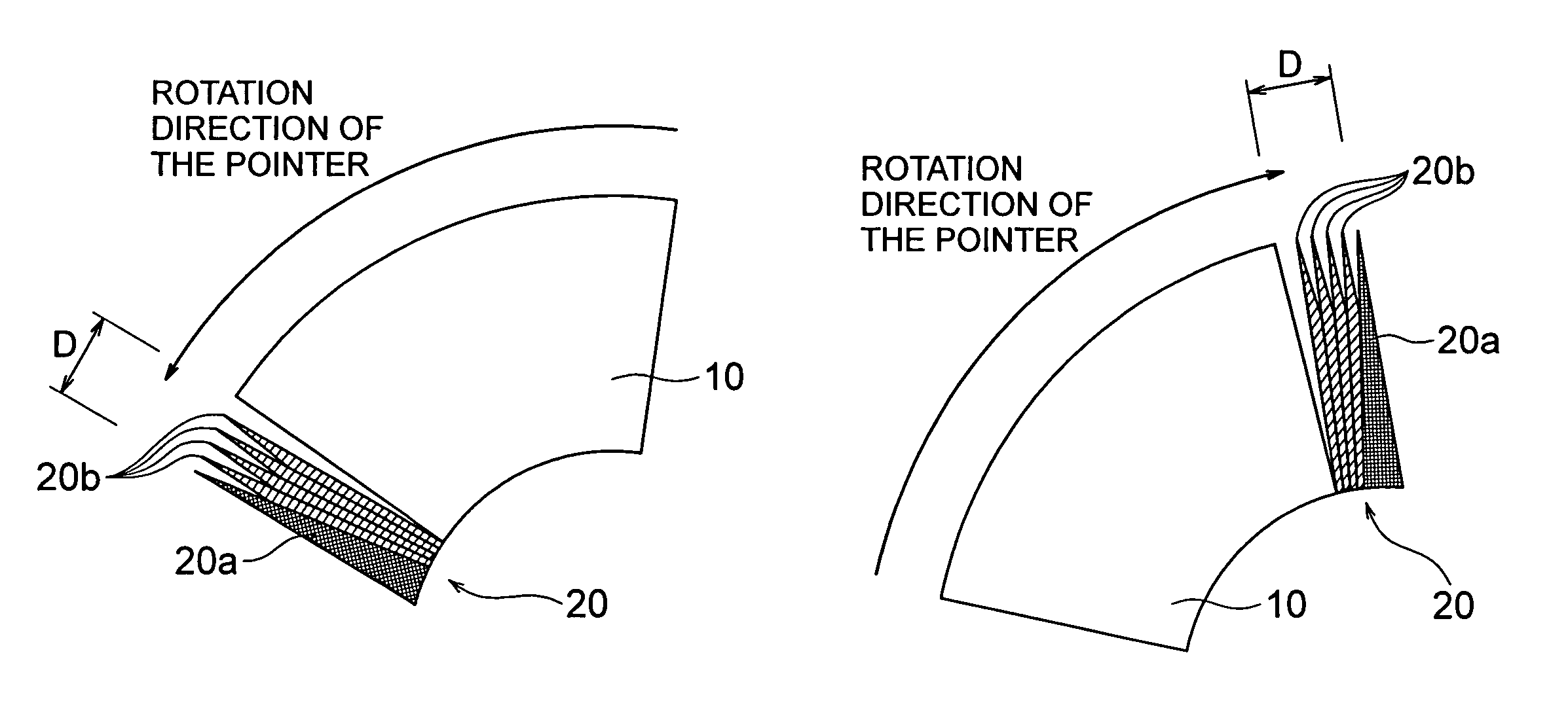
[0031]In accordance with the first embodiment, since multiple pointer images where a plurality of the pointer images are aligned with one another are displayed adjacent to or in abutment with a leading part of the motion blur pointer image in a direction where the pointer is rotating, when the motion blur pointer image is switched to the normal pointer image, in the case of being viewed by a vehicle operator, the motion blur pointer image and the normal pointer image seem to be arranged consecutively with each other by the presence of the multiple pointer images intervening therebetween. Accordingly, the vehicle operator can be prevented from feeling inconvenience while the motion blur display mode is switched to the normal display mode.

second embodiment

[0032]In accordance with the second embodiment, the multiple pointer images are easily to be displayed corresponding to the space between the motion blur pointer image and the normal pointer image.

third embodiment

[0033]In accordance with the third embodiment, since multiple pointer images where a plurality of the pointer image are aligned with one another are displayed adjacent to or in abutment with a leading part of the motion blur pointer image in a direction where the pointer is rotating, when the motion blur pointer image is switched to the normal pointer image, in the case of being viewed by a vehicle operator, the motion blur pointer image and the normal pointer image seem to be arranged consecutively with each other by the presence of the multiple pointer images intervening therebetween. Accordingly, the vehicle operator can be prevented from feeling inconvenience while the motion blur display mode is switched to the normal display mode. In addition to the afore-mentioned advantageous effect, the vehicle operator can hardly recognize the space between the motion blur pointer image and the normal pointer image, when the motion blur pointer image is switched to the normal pointer image...


PUM


Abstract

The object of the invention is to provide an improved graphic display meter which is prevented from causing inconvenience to the vehicle operator, when a motion blur display mode is switched to a normal display mode.When a motion blur pointer image 10 is switched to a normal pointer image 20a, multiple pointer images 20 including the normal pointer image 20a are displayed adjacent to or in abutment with a leading part of the motion blur pointer image 10 in a direction where the pointer is rotating. The multiple pointer images 20 are consisted of the normal pointer image 20a and a plurality of auxiliary pointer images 20b, which are aligned with one another and are positioned in close proximity to the normal pointer image 20a. The multiple pointer images 20, a plurality set of which have been stored as data in advance, are selected on the basis of a space between the motion blur pointer image 10 prior to the switching of the pointer image and the normal pointer image 20 after the switching of the pointer image.

Description

CROSS-REFERENCE TO RELATED APPLICATIONS[0001]The present Application claims priority to Japanese Patent Application No. 2006-176354 filed Jun. 27, 2006, the entire disclosure of which, including the specification and drawings, is expressly incorporated herein by reference.BACKGROUND OF THE INVENTION[0002](1) Field of the Invention[0003]The present invention relates to a graphic display meter for providing graphical vehicle driving related information, by displaying a dial and a pointer on a display device thereof such as a liquid crystal display (LCD) in the form of a dot matrix. Accordingly, the present invention is particularly suitable for use with an automotive vehicle.[0004](2) Description of the Related Art[0005]In conventional graphic display meters, in a case where the pointer is driven to rotate rapidly, too many images of the pointer including its after-images are displayed thereon, causing inconvenience to a vehicle user. To solve the above discussed problem, there has be...

Claims


Application Information

Patent Timeline
Patent Type & Authority Patents(United States)
IPC IPC(8): G06T11/00B60K35/00G01D7/00
CPCB60K35/00G01D7/00G12B11/02B60K2350/1072B60K2370/155
Inventor KATOH, HIROSHINAGAHASHI, KENICHI
Owner YAZAKI CORP
Why Eureka
Try Eureka