Fluid dispensing apparatus and method

a technology dispensing apparatus, which is applied in the direction of liquid transferring device, process and machine control, instruments, etc., can solve the problems of cost prohibitive installation of this type of equipment, and may be difficult to achiev

Active Publication Date: 2013-01-01
JOHNSONDIVERSEY INC
View PDF70 Cites 13 Cited by
  • Summary
  • Abstract
  • Description
  • Claims
  • Application Information

AI Technical Summary

Problems solved by technology

However, installation of this type of equipment can be cost prohibitive.
This, however, may be difficult when filling or only partially filling sinks, reservoirs within a floor cleaning machine, buckets, and various other containers.

Method used


Image

  • Fluid dispensing apparatus and method
  • Fluid dispensing apparatus and method
  • Fluid dispensing apparatus and method

Examples


Embodiment Construction

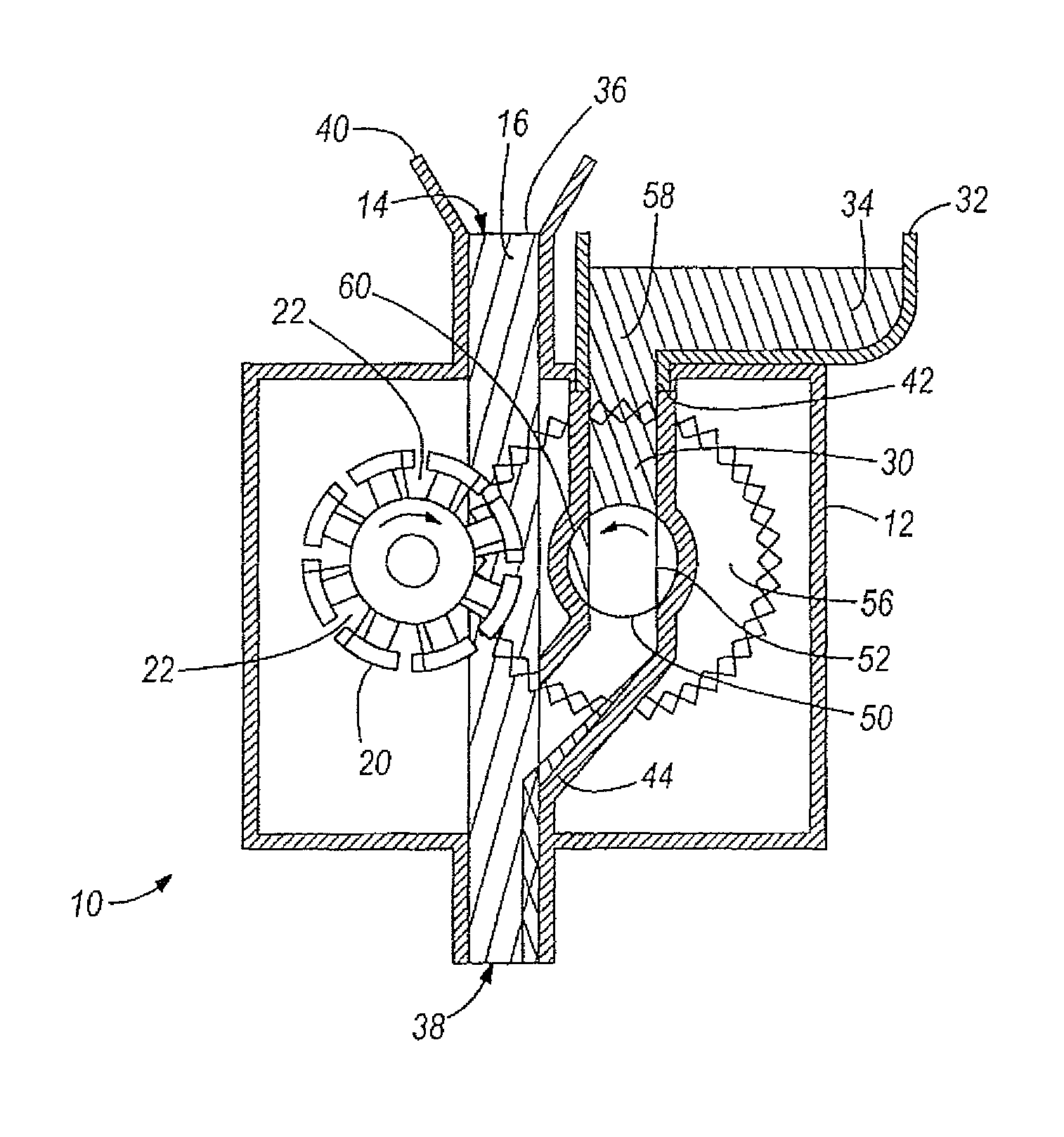
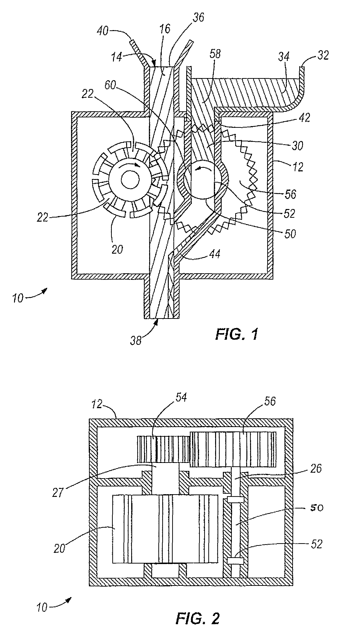
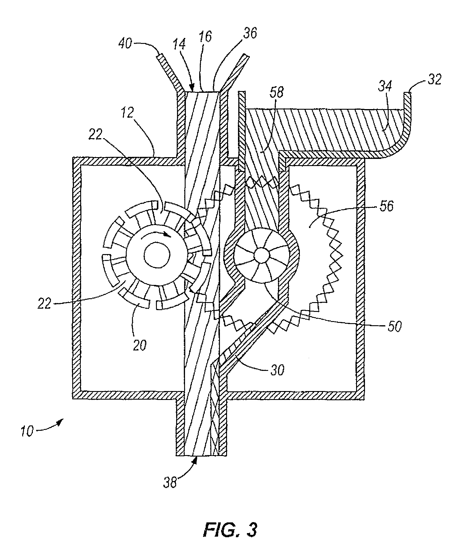
[0061]Referring to FIGS. 1 and 2, an embodiment of a dispensing apparatus 10 embodying aspects of the present invention is illustrated. The illustrated dispensing apparatus 10 provides a dilution control system that doses volumetrically. In other words, the dispensing apparatus 10 of this embodiment draws or otherwise delivers a concentrated chemical proportionally to the flow rate of a diluent passing through the dispensing apparatus 10 and into a container.

[0062]As illustrated, the dispensing apparatus 10 of this embodiment has a housing 12 and a fluid passageway 14 through which a diluent 16 from a diluent source (not shown) passes. The diluent source can be, for example, a plumbed diluent source such as a faucet on a sink or a spigot, a hose or hose bib, a pipe or other conduit, and the like, or can instead be a vessel of any type. In some embodiments, the fluid passageway 14 is defined at least in part by a portion of the housing 12, whereas in other embodiments, the fluid pass...


PUM


Abstract

A fluid dispenser and method of operating the same. The fluid dispenser can include a wheel driven by diluent passing along a flow path in the fluid dispenser. The wheel can be connected to a pump to pump fluid from a reservoir for dispense into the diluent. In some embodiments, the ratio of wheel rotations to pump cycles is selected to provide a desired and repeatable dilution ratio of concentrated fluid to diluent. The fluid dispenser can be portable and / or disposable, and in some embodiments is adapted for installation on an upper rim of a reservoir wall. Also, the fluid dispenser can be provided with a baffle limiting the velocity and impact of incoming diluent to the wheel driving the pump, thereby improving dosing accuracy of the dispenser in some embodiments.

Description

CROSS-REFERENCE TO RELATED APPLICATIONS[0001]This application is a Continuation of International Application No. PCT / US2007 / 020511, filed on Sep. 21, 2007, which claims priority to International Application No. PCT / US2007 / 064524 filed on Mar. 21, 2007, which claims priority to U.S. Provisional Patent Application Ser. No. 60 / 784,969 filed on Mar. 22, 2006. The entire contents of all earlier-filed patent applications are incorporated herein by reference.BACKGROUND OF THE INVENTION[0002]Many different types of dosing equipment are used to dose concentrated cleaning chemicals and other types of chemicals into a final use solution at a predetermined dilution ratio. Some types of equipment are plumbed directly to a water source (i.e., volumetric eductor based dispensing). However, installation of this type of equipment can be cost prohibitive. Other types of equipment utilize portion control, wherein a predetermined amount of concentrated chemicals is dispensed into a mixing container and...

Claims


Application Information

Patent Timeline
Patent Type & Authority Patents(United States)
IPC IPC(8): B67D1/00
CPCG05D11/006G05D11/008Y10T137/2516Y10T137/2496B05C11/00A61L9/05
Inventor BERTUCCI, MICHAEL H.LANG, CHRISTOPHER F.LEWIS, SUSAN K.NUNEZ, JUSTIN M.JONES, TIMOTHY S.SCHILLER, STEVEN E.PHILLIPS, WAYNE
Owner JOHNSONDIVERSEY INC
Why Eureka
Try Eureka