
Plunger lift mechanism

Inactive Publication Date: 2013-01-08
4S OILFIELD TECH
View PDF14 Cites 34 Cited by
  • Summary
  • Abstract
  • Description
  • Claims
  • Application Information

AI Technical Summary

Benefits of technology

This patent is about devices and methods used to maintain the operation of drilling equipment. The patent describes a plunger lift mechanism which uses a main channel with two valves to efficiently pump fluids out of a well. By closing the valves and accumulating pressure, the plunger lift is forced to move and evacuate any fluids above it. The technical effect of this invention is to provide a reliable and efficient way to maintain the operation of drilling equipment.

Problems solved by technology

These clutch mechanisms wear out over time, and in certain wells, especially those with low pressure or low flow rates, the pressure from the fluid column being lifted can overcome the clutch mechanism, causing the valve to open, sending the plunger and fluid column back to the bottom of the well.

Method used


Image

  • Plunger lift mechanism
  • Plunger lift mechanism
  • Plunger lift mechanism

Examples


Embodiment Construction

[0018]Reference will now be made in detail to one or more examples of the invention depicted in the figures. Each example is provided by way of explanation of the invention, and not meant as a limitation of the invention. For example, features illustrated or described as part of one embodiment may be used with another embodiment to yield still a different embodiment. Other modifications and variations to the described embodiments are also contemplated within the scope and spirit of the invention.

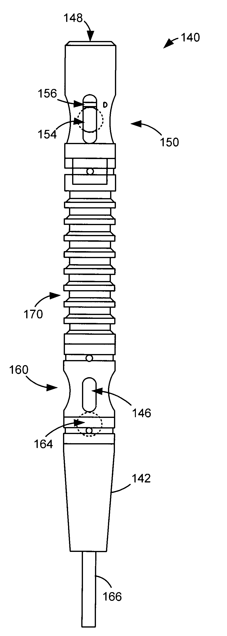
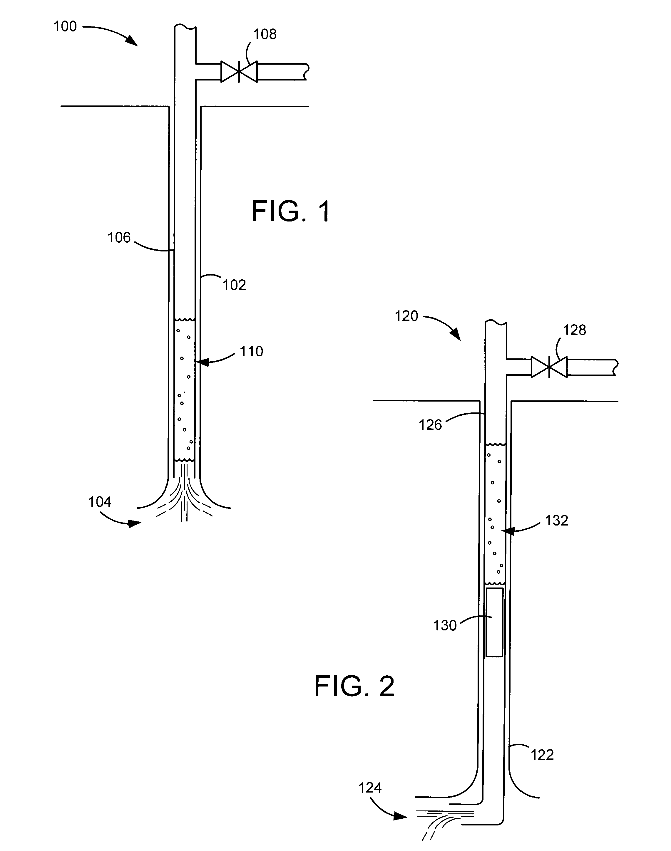
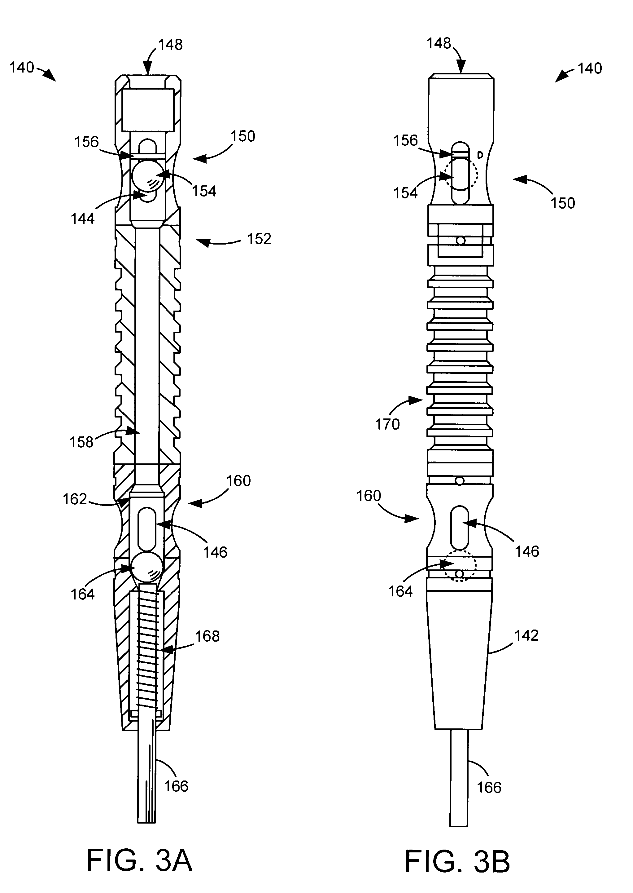
[0019]In operation, the accumulations of fluids in natural gas well casings can restrict the flow by exerting high pressure on the face of a producing formation. One relatively inexpensive method for removing such accumulations of fluids is the use of a plunger lift which includes a piston that is dropped into the well and then moved upwardly to lift the liquid to the surface. Such plunger lifts can include a valve which is held in a closed position by pressure from the produced liquids and ...


PUM


Abstract

Method and apparatus for a plunger lift mechanism with a main channel disposed between a first and second valve. The first valve is closed by engaging a sealing member to a first seat at a proximal end of the main channel and the second valve consequently closes to with a sealing member engaging a second seat at a distal end of the main channel. An amount of pressure accumulates on a first side of the plunger lift to overcome a pressure on a second side of the plunger lift to force the plunger lift to traverse a well bore and evacuate any fluids present above the plunger lift.

Description

RELATED APPLICATIONS[0001]This application claims priority to U.S. Provisional Application No. 61 / 229,173 filed Jul. 28, 2009, entitled “Plunger Lift Mechanism.”FIELD OF THE INVENTION[0002]The claimed invention relates to the field of downhole well equipment and operations and more particularly to clearing liquids from a downhole low pressure environment.BACKGROUND[0003]The accumulation of fluids in natural gas well casings, i.e., flowback, restricts the flow by exerting high pressure on the face of the producing formation. One relatively inexpensive method for removing such accumulations of fluids is the use of a plunger lift, which is dropped into the well and then moved upwardly by the formation pressure to lift the liquid in the well casing to the surface. Prior art plunger lifts include a valve held in the closed position by pressure from the produced liquids and gases below the plunger and by a clutch mechanism. These clutch mechanisms wear out over time, and in certain wells,...

Claims


Application Information

Patent Timeline
IPC IPC(8): E21B43/00
CPCE21B43/121
Inventor SEWELL, MICHAELSTEPHENS, AMY C.
Owner 4S OILFIELD TECH
Features
  • Generate Ideas
  • Intellectual Property
  • Life Sciences
  • Materials
  • Tech Scout
  • Unparalleled Data Quality
  • Higher Quality Content
  • 60% Fewer Hallucinations
Learn More