Tensioning device for a carrying net

a technology of tensioning device and carrying net, which is applied in the direction of waterborne vessels, floating buildings, vessel construction, etc., can solve the problems of difficult adhesion of advantageous tensioning force, and achieve the effect of simplifying design

Inactive Publication Date: 2013-01-22
BIERMA JOCHUM
View PDF12 Cites 0 Cited by
  • Summary
  • Abstract
  • Description
  • Claims
  • Application Information

AI Technical Summary

Benefits of technology

[0008]In order to simplify the design, the tensioning leg can have a profile forming a longitudinal groove for receiving an edge portion of the carrying net and two end caps, forming the pivot bearings for the tensioning leg, for the profile, at least one of the end caps being provided with the part of the interlocking means that is associated with the tensioning leg. This measure allows the tensioning leg to be adapted in a simple manner to the respective length of the net in that the profile is cut to length accordingly. The end caps, which can be placed into or onto the profile, have all the design parts that are required for the mounting and interlocking of the tensioning leg in the tensioning frame. These end caps can also close off the groove for receiving the edge strip of the carrying net, so that no additional measures are required for axially securing the carrying net. As, in dismantlable catamarans, the tensioning frame is generally also dismantled, it is advisable to connect the tensioning leg to the tensioning frame in a releasable manner. For this purpose, the pivot bearings in the end caps of the tensioning leg can form open bearing half-shells, allowing simple detachment of the tensioning leg from the stubs of the pivot shaft. In the tensioning position, the bearing half-shells are pulled toward these shaft stubs, thus ensuring a secure hold for the tensioning leg within the tensioning frame.

Problems solved by technology

This involves laboriously tensioning the carrying net by hand before the net is fastened; this makes an advantageous tensioning force difficult to adhere to.

Method used


Image

  • Tensioning device for a carrying net
  • Tensioning device for a carrying net
  • Tensioning device for a carrying net

Examples


Embodiment Construction

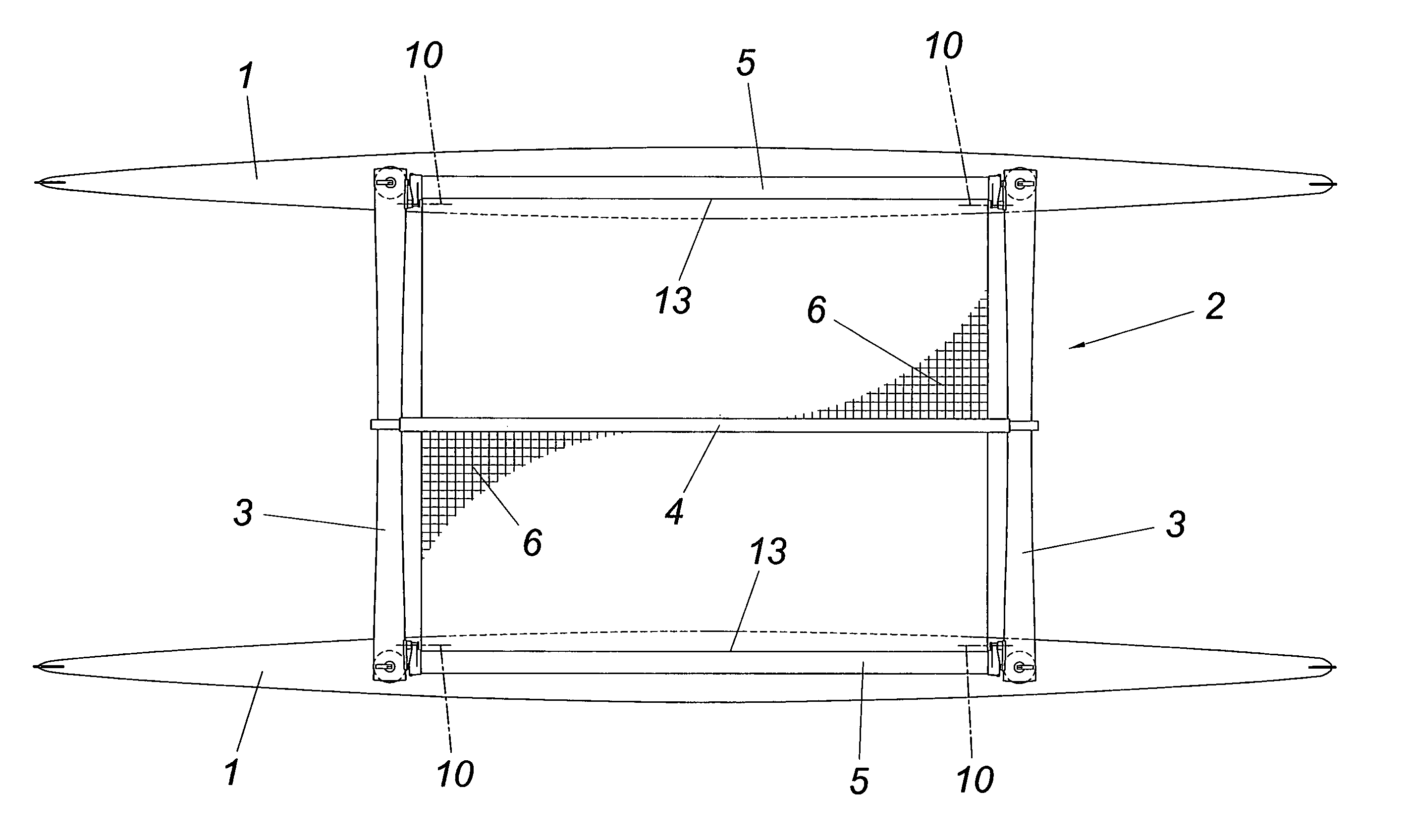
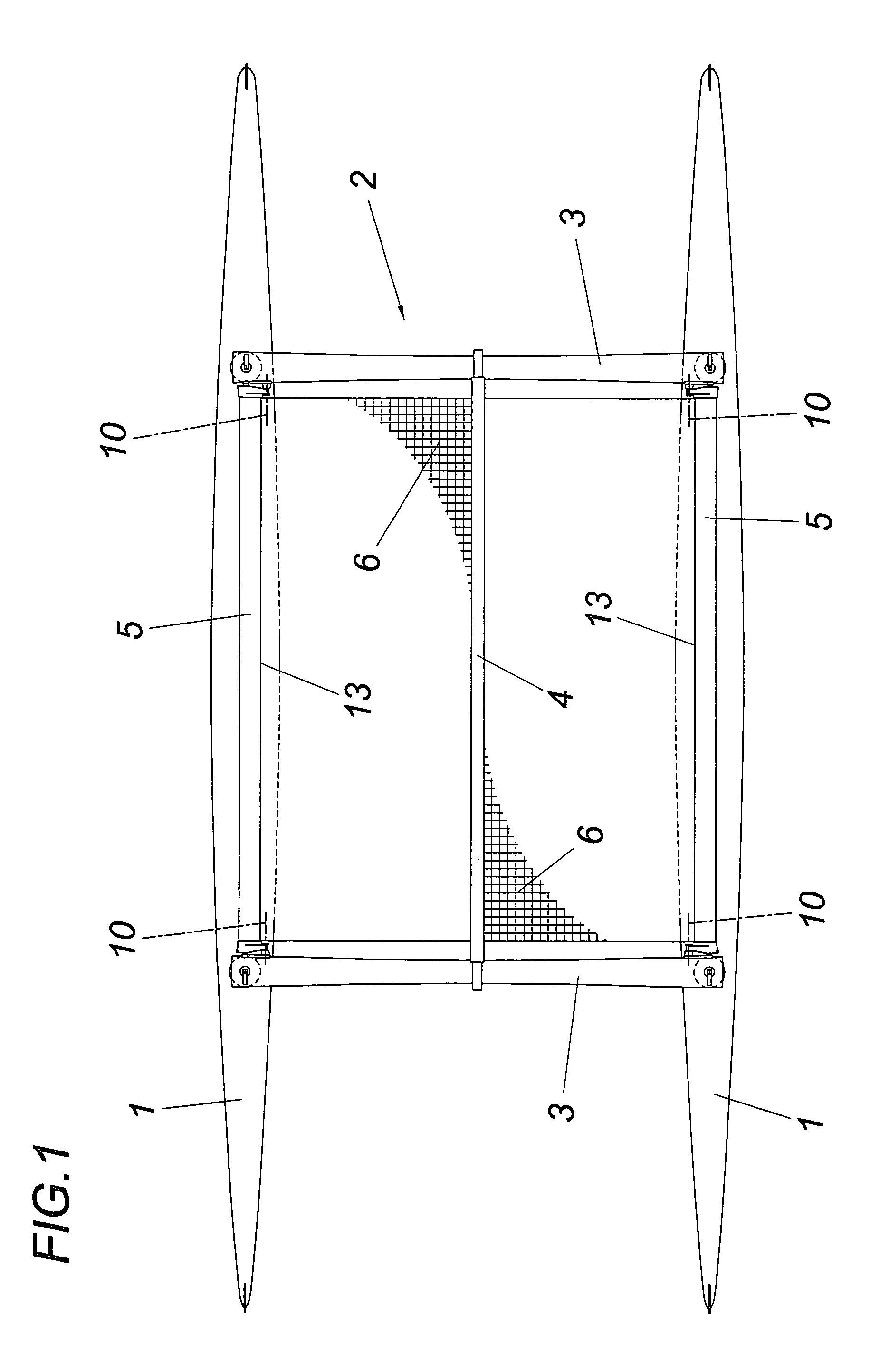
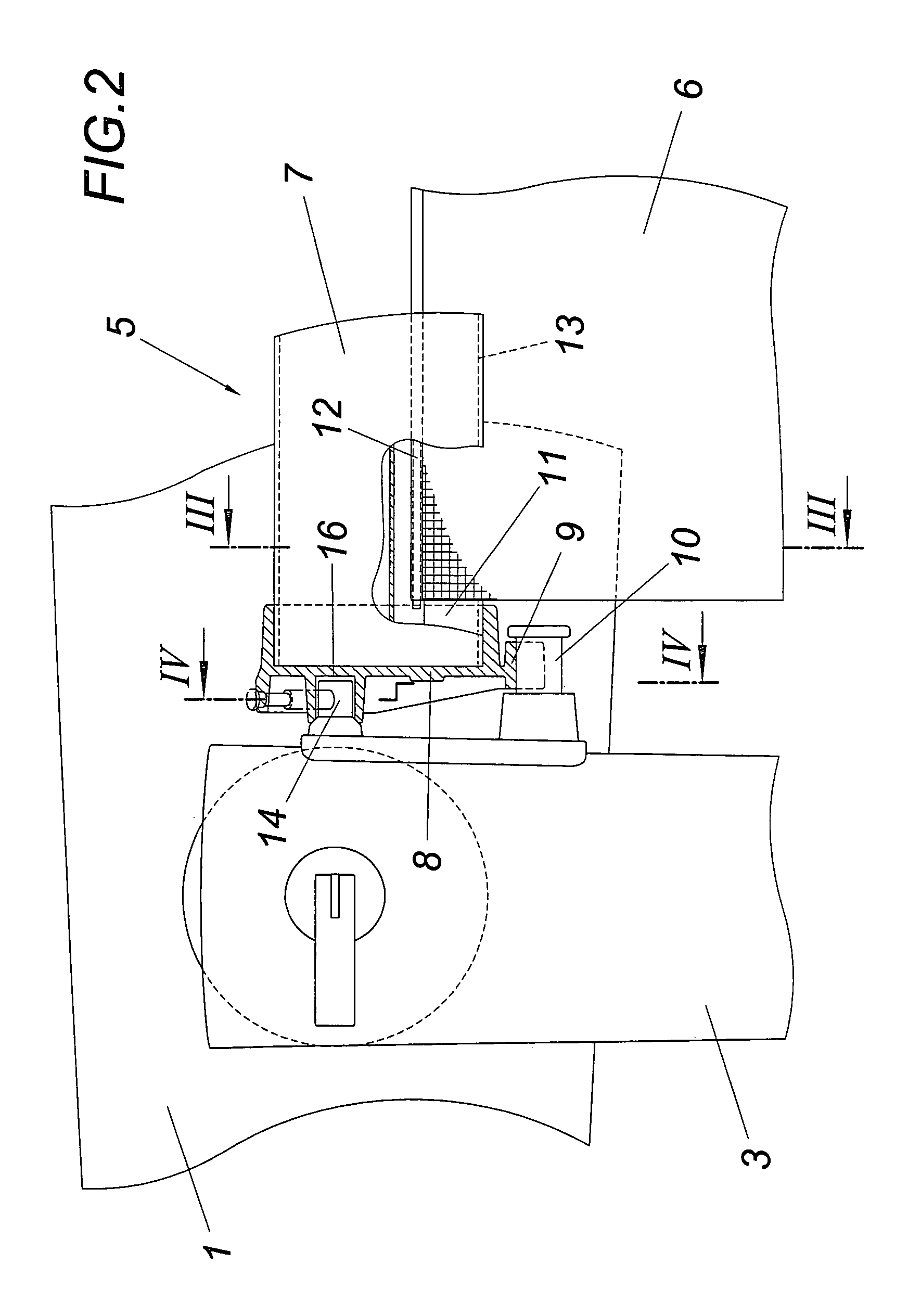
[0014]According to FIG. 1, the illustrated catamaran has two hulls 1 which are releasably joined together by a cradle 2. This cradle 2 has two connecting struts 3 which carry a central longitudinal beam 4 and receive, at the end side, tensioning legs5 which each form with the longitudinal beam 4 and the connecting struts 3 a tensioning frame for a carrying net 6. The two carrying nets 6 are each connected to the longitudinal beam 4 and the associated tensioning leg 5 in a tensile-resistant manner. The tensioning legs 5 are each composed of a profile 7 and end caps 8 which close off the profile 7 at the end side and form a bearing half-shell 9 for pivotable support on a pivot shaft 10 formed by shaft stubs on the connecting struts 3. The profile 7 comprises a longitudinal groove 11 for receiving an edge portion of the carrying net 6 which is secured in the longitudinal groove 11 by means of a beading 12.

[0015]As may be seen in particular from FIGS. 2 and 3, the pivot shaft 10 for the...


PUM


Abstract

A tensioning device is described for a carrying net (6), in particular between the hulls (1) of a catamaran, the carrying net (6) being fastened in a tensile-resistant manner to two mutually opposing legs of a tensioning frame. In order to attain advantageous tensioning conditions, it is proposed that one of the two legs be mounted, as the tensioning leg (5), in the tensioning frame so as to be rotatable about a pivot shaft (10) which is parallel to its longitudinal axis, the pivot shaft extending, when the carrying net (6) is tensioned, on the net side at a distance from the run-off line (13) of the carrying net (6) from the tensioning leg (5), and that an interlocking means (15) be provided for the tensioning position of the tensioning leg (5).

Description

CROSS REFERENCE TO RELATED APPLICATIONS[0001]Applicant claims priority under 35 U.S.C. §119 of Austrian Application No. A 1737 / 2008 filed on Nov. 10, 2008.FIELD OF THE INVENTION[0002]The invention relates to a tensioning device for a carrying net, in particular between the hulls of a catamaran, the carrying net being fastened in a tensile-resistant manner to two mutually opposing legs of a tensioning frame.DESCRIPTION OF THE PRIOR ART[0003]In catamarans, the cradle, which joins the two hulls together, often has at least one carrying net which bridges the gap between the two hulls and is tensioned between mutually opposing legs of a tensioning frame formed by the connecting cradle. This carrying net is connected in a tensile-resistant manner to the mutually opposing tensioning frame legs, wherein the carrying net can be clamped or tied down. This involves laboriously tensioning the carrying net by hand before the net is fastened; this makes an advantageous tensioning force difficult ...

Claims


Application Information

Patent Timeline
Patent Type & Authority Patents(United States)
IPC IPC(8): B63B1/10B63B1/12
CPCB63B1/121B63B17/00
Inventor BIERMA, JOCHUM
Owner BIERMA JOCHUM
Why Eureka
Try Eureka