
Device fabrication with planar bragg gratings suppressing parasitic effects

a technology of planar bragg grating and device fabrication, which is applied in the field of method of fabricating planar bragg grating, can solve the problems of unwanted parasitic grating, formation of parasitic grating, and difficulty in fabricating bragg grating in planar waveguides, and achieve the effect of suppressing unwanted parasitic grating effects

Active Publication Date: 2013-01-22
OPTASENSE
View PDF8 Cites 3 Cited by
  • Summary
  • Abstract
  • Description
  • Claims
  • Application Information

AI Technical Summary

Benefits of technology

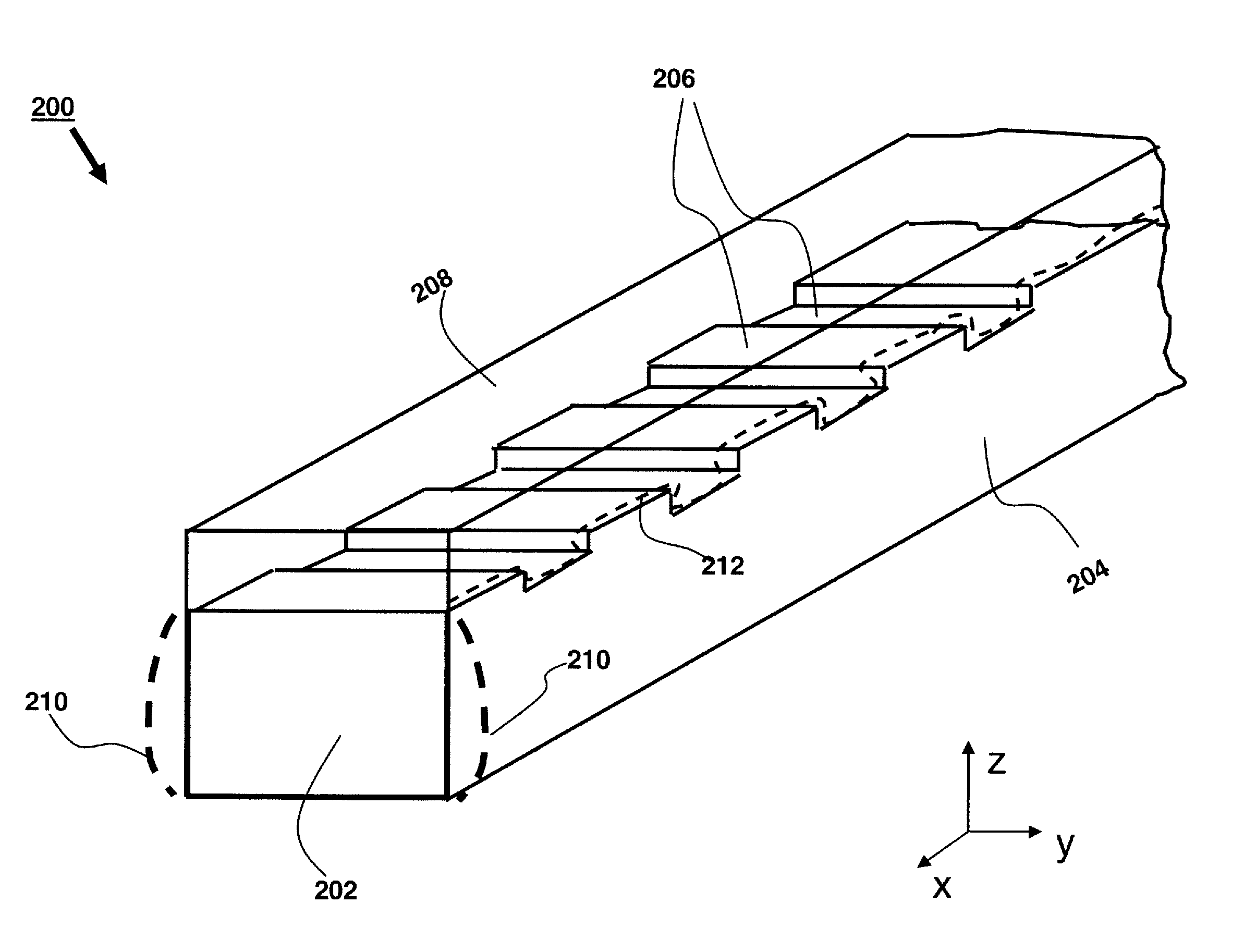
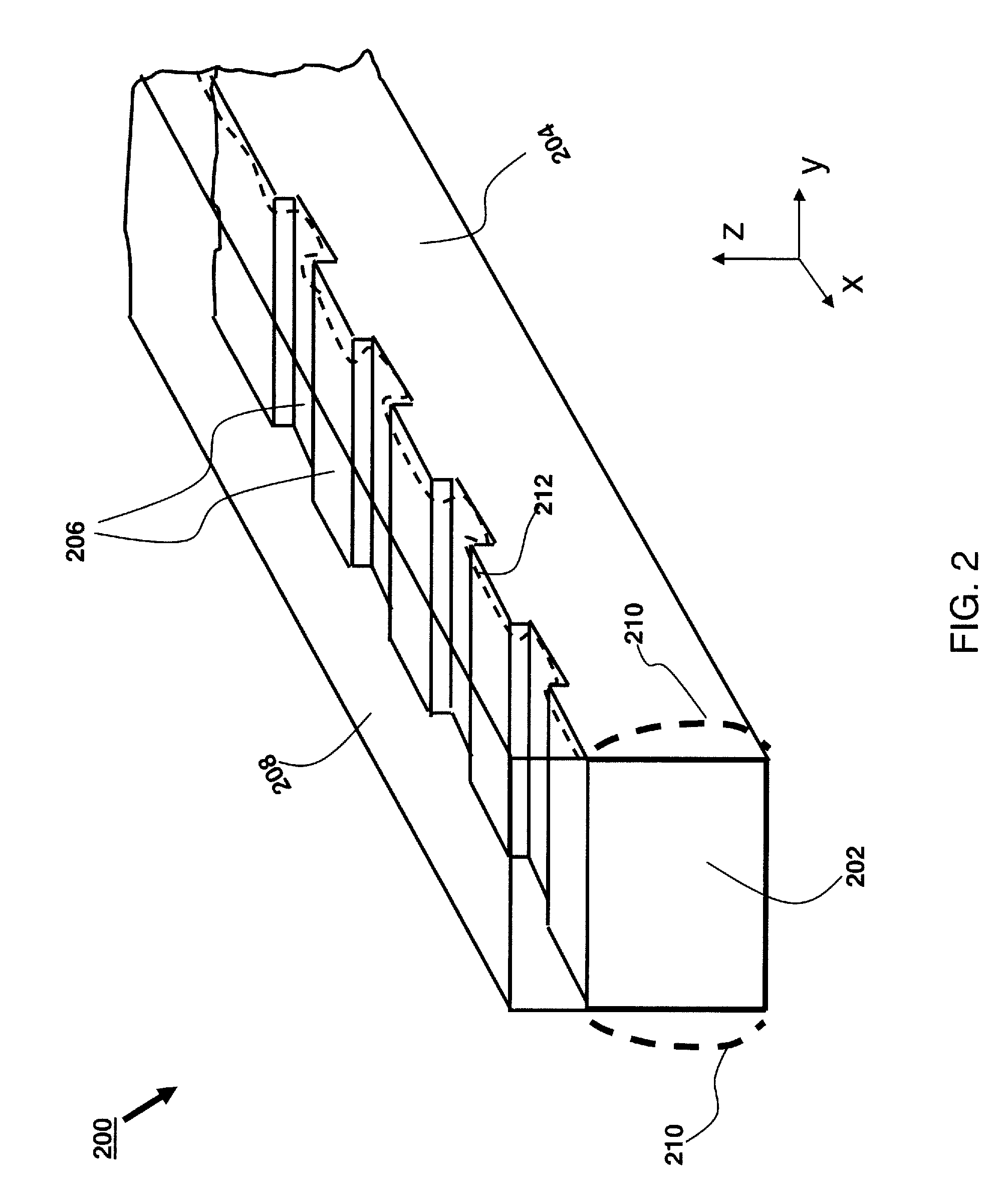
[0009]The present invention relates to various methods of fabricating Planar Bragg Gratings (PBG) in a doped waveguide in a Planar Lightwave Circuit (PLC) device, suppressing unwanted parasitic grating effects during fabrication of the device.
[0010]According to one aspect, the present invention discloses a method for fabricating a planar lightwave circuit (PLC) device, the method comprising: selectively doping an area of a core layer with a dopant to define a core area of a waveguide; preparing Bragg grating corrugations on top of the core area across a predefined width of the waveguide; forming a barrier layer on top of the Bragg grating corrugations, wherein a material of the harrier layer is selected to prevent outdiffusion of the dopant into the barrier layer; lithographically patterning a top surface of the PLC device to cover the Bragg grating corrugations underneath during subsequent etching; etching through the barrier layer and through the core layer to expose waveguide sidewalls; encompassing the core area at least partially with a cladding material; and annealing the PLC device at a high temperature, allowing outdiffusion of the dopant from the core area into the cladding material, thereby smoothening the waveguide sidewalls.
[0011]In furtherance of these and other aspects, a planar lightwave circuit (PLC) device is disclosed, comprising: a core area of a waveguide doped with a dopant, wherein the core area is at least partially encompassed with a cladding material; Bragg grating corrugations on top of the core area across a predefined width of the waveguide; and a barrier layer on top of the Bragg grating corrugations, wherein a material of the barrier layer is selected to prevent outdiffusion of the dopant into the barrier layer; wherein when the PLC device is annealed at a high temperature, allowing outdiffusion of the dopant from the core area into the cladding material, waveguide sidewalls are smoothened, avoiding parasitic gratings on the waveguide sidewalls.
[0012]According to another aspect, the present invention discloses a method for fabricating a planar lightwave circuit (PLC) device, the method comprising: defining a core area in a core layer of a waveguide; preparing Bragg grating corrugations on top of the core area across a predefined width of the waveguide; forming a Bottom Anti Reflective Coating (BARC) layer on top of the Bragg grating corrugations, wherein the BARC layer substantially planarizes the Bragg gating corrugations; hard-baking the BARC layer, where parameters of the hard-baking step are controlled to tailor an undercut of a photoresist layer at an interface with the BARC layer during subsequent photolithography; photolithographically patterning a top surface of the PLC device to cover the Bragg grating corrugations with the photoresist layer and the BARC layer during subsequent etching; etching through the core layer to expose waveguide sidewalls, wherein undesired parasitic gratings are prevented from being formed during the etching step due to the undercut of the photoresist layer at the interface with the BARC layer.
[0013]According to yet another aspect, the present invention discloses a method for fabricating a planar lightwave circuit (PLC) device, the method comprising: defining a buffer layer; preparing an Bragg grating corrugations on top of the buffer layer across a predefined width of a waveguide; depositing a core layer on top of the buffer layer to embed the Bragg grating corrugations; lithographically patterning the core layer to cover the predefined width of the waveguide with the embedded Bragg grating corrugations; and etching through the core layer to expose waveguide sidewalls, wherein undesired parasitic gratings are prevented from being formed during the etching step due to the embedding of the Bragg grating corrugations.

Problems solved by technology

While the manufacturing of Bragg gratings by using holographic exposure of optical fiber has been well established, the manufacturing of Bragg grating in planar waveguides has encountered a number of challenges, including unwanted parasitic gratings, as will be described further below.
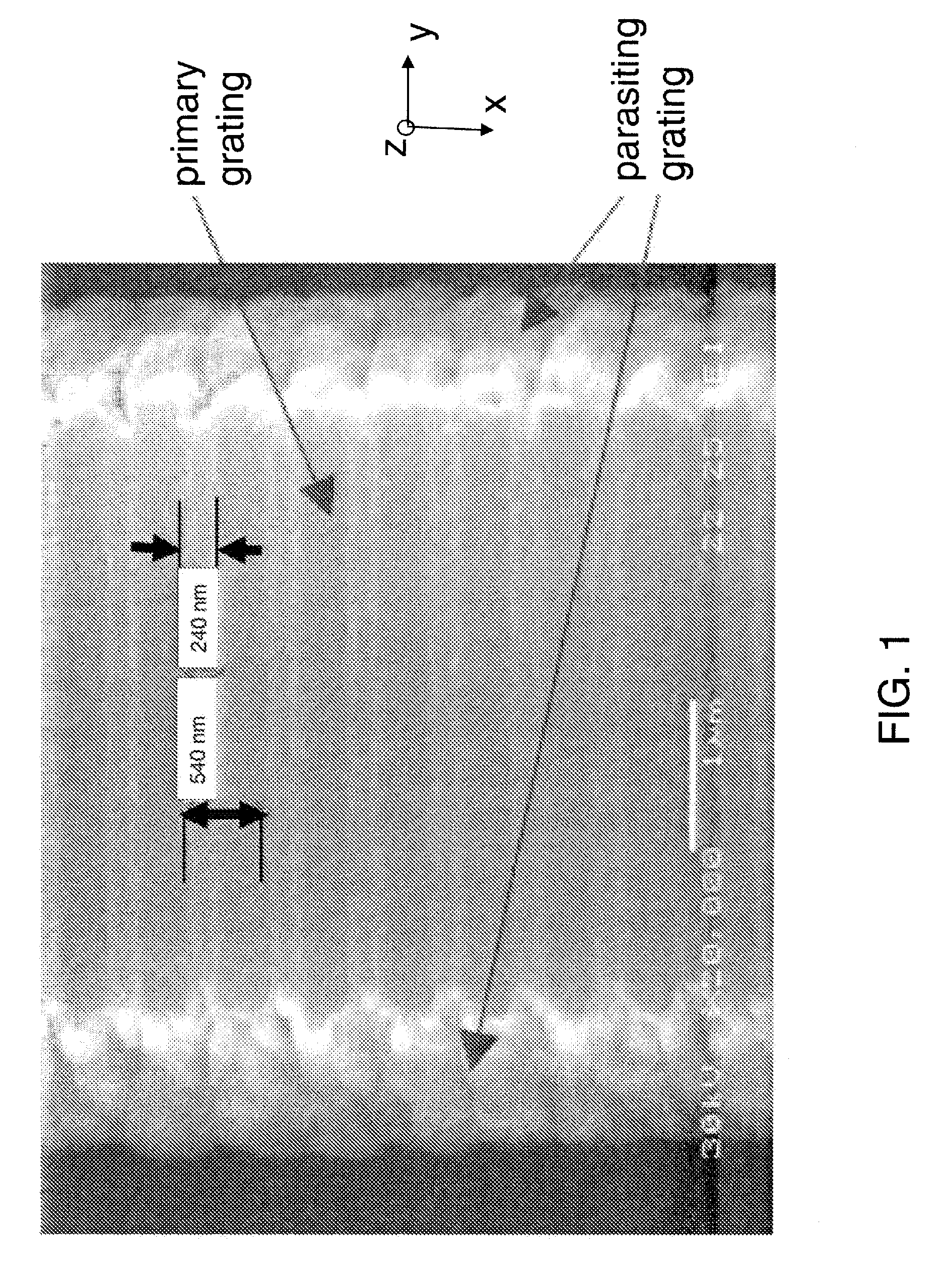
It is believed that the cause of the formation of the parasitic gratings is an interaction of the reactive ion etching reactants with the non-uniform photo resist layer used to mask the corrugated wave guide during waveguide etch.
The out-of-phase parasitic grating has the effect of weakening or canceling out altogether the reflectance of the primary grating etched at the top of the waveguide, leading to uncontrolled optical performance of the Bragg grating, and the PLC device.
In addition to the problem of sidewall parasitic grating affecting the primary grating performance, a related problem observed during the fabrication of PBGs is outdiffusion of dopant from the core area to adjacent cladding or buffer materials during high-temperature (e.g., 800-100° C. or higher temperature) annealing.
In case of germanium-doped silica core, the outdiffusion problem is particularly prominent, because at high annealing temperature, germanium can diffuse to distances on the order of 1 micron or more depending on the cladding material, which may result in erasure of refractive index variation created by the etched grating corrugations, if the outdiffusion is not prevented in certain directions.

Method used


Image

  • Device fabrication with planar bragg gratings suppressing parasitic effects
  • Device fabrication with planar bragg gratings suppressing parasitic effects
  • Device fabrication with planar bragg gratings suppressing parasitic effects

Examples


Embodiment Construction

[0024]The present invention will now be described in detail with reference to the drawings, which are provided as illustrative examples of the invention so as to enable those skilled in the art to practice the invention. Notably, the figures and examples below are not meant to limit the scope of the present invention to a single embodiment, but other embodiments are possible by way of interchange of some or all of the described or illustrated elements. Moreover, where certain elements of the present invention can be partially or fully implemented using known components, only those portions of such known components that are necessary for an understanding of the present invention will be described, and detailed descriptions of other portions of such known components will be omitted so as not to obscure the invention. In the present specification, an embodiment showing a singular component should not be considered limiting; rather, the invention is intended to encompass other embodimen...


PUM


Abstract

The present invention relates to various methods of fabricating Planar Bragg Gratings (PBG) in a doped waveguide in a Planar Lightwave Circuit (PLC) device, suppressing unwanted parasitic grating effects during fabrication of the device. One approach to reduce parasitic gratings is to use a hard mask before the waveguide photolithography and etch, that results in a steeper sidewall angle that reduces or eliminates the parasitic grating effect. Another method of reducing parasitic grating effect is to deposit a layer of developable Bottom Anti Reflective Coating (BARC) prior to depositing the photo resist for waveguide etch. A third method of resisting parasitic gratings comprises using a planarizing undoped silica layer as a barrier layer on top of the core. During subsequent high temperature annealing germanium outdiffuses laterally into the cladding. The net effect is an optical waveguide with improved lateral uniformity because germanium diffusion smoothes out the sidewall roughness created during the waveguide reactive ion etch process. The undoped silica (SiO2) layer on top of the grating also serves the purpose of significantly reducing germanium outdiffusion from the core in the upward direction.

Description

CROSS REFERENCE TO RELATED APPLICATION[0001]This application claims priority from U.S. Provisional Application Ser. No. 61 / 181,617 filed May 27, 2009.FIELD OF THE INVENTION[0002]The present invention relates to methods of fabricating Planar Bragg Gratings (PBG) in a doped waveguide in a Planar Lightwave Circuit (PLC) device.BACKGROUND[0003]Bragg gratings have a number of important applications in optical components, such as, lasers, sensors, dispersion compensation devices, etc. There are many ways to manufacture Bragg gratings on an optical fiber or in a planar waveguide. A Bragg grating comprises a number of partially reflecting elements imprinted or embedded onto the light guiding element (e.g., optical fiber or optical waveguide). While the manufacturing of Bragg gratings by using holographic exposure of optical fiber has been well established, the manufacturing of Bragg grating in planar waveguides has encountered a number of challenges, including unwanted parasitic gratings, a...

Claims


Application Information

Patent Timeline
Patent Type & Authority Patents(United States)
IPC IPC(8): G02B6/34
CPCG02B6/132G02B6/134B82Y20/00G02B6/12007G02B6/1225G02B6/124
Inventor BARSAN, RADUSTOLPNER, LEW
Owner OPTASENSE
Learn More