
Method and apparatus for harvesting energy

a technology of energy harvesting and energy storage, applied in the direction of electrochemical generators, secondary cells servicing/maintenance, transportation and packaging, etc., can solve the problems of inefficiency, high cost, and large size of most energy harvesting equipmen

Active Publication Date: 2013-01-29
VOXX INTERNATIONAL
View PDF39 Cites 319 Cited by
  • Summary
  • Abstract
  • Description
  • Claims
  • Application Information

AI Technical Summary

Benefits of technology

The present invention is an energy harvesting device that can be charged from an external power source such as a battery or a power transformer. This allows the device to be constantly powered without the need for a separate battery. The energy harvesting device can be connected to a variety of external power sources such as a cigarette lighter or a wall power receptacle. The charging of the device can be done by providing the external power source to the internal storage device through a circuit. The technical effect of this invention is that it provides a convenient and reliable way to power portable devices without the need for batteries or separate charging equipment.

Problems solved by technology

Except for solar cells powering hand held calculators and other small electronic devices, most energy harvesting apparatus are relatively large, expensive and inefficient.

Method used


Image

  • Method and apparatus for harvesting energy
  • Method and apparatus for harvesting energy
  • Method and apparatus for harvesting energy

Examples


Embodiment Construction

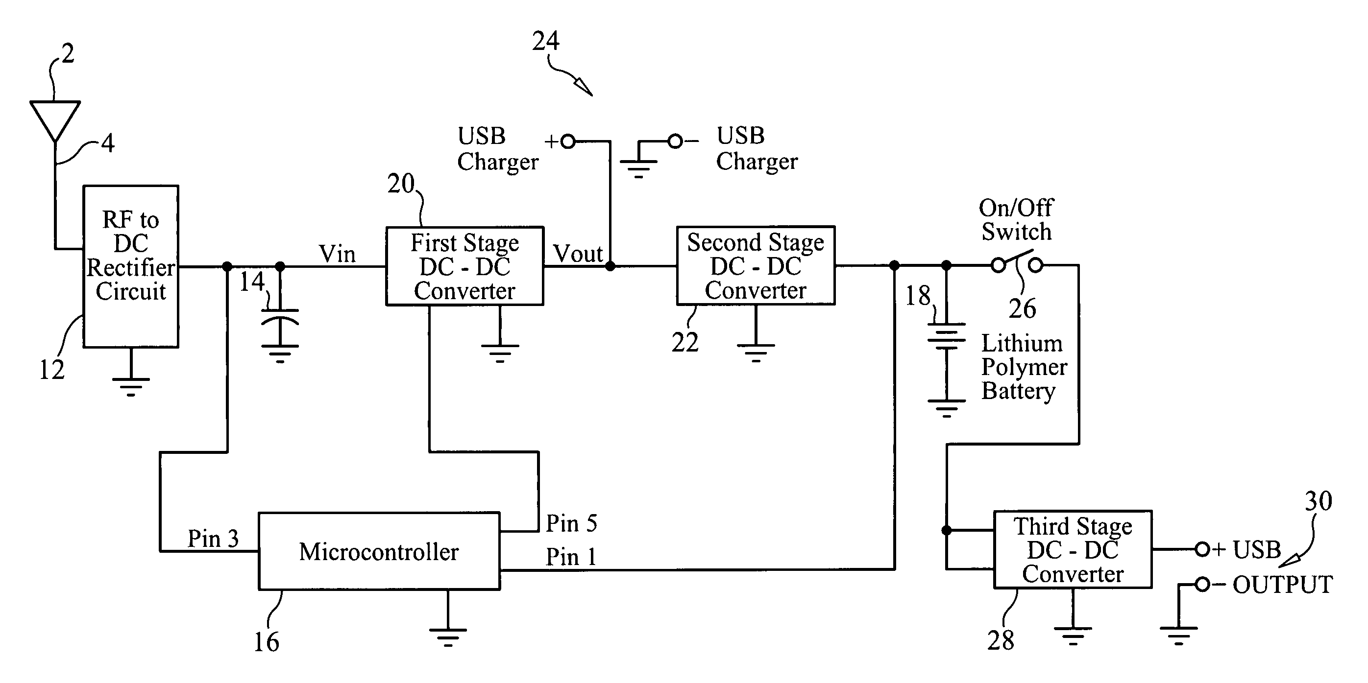
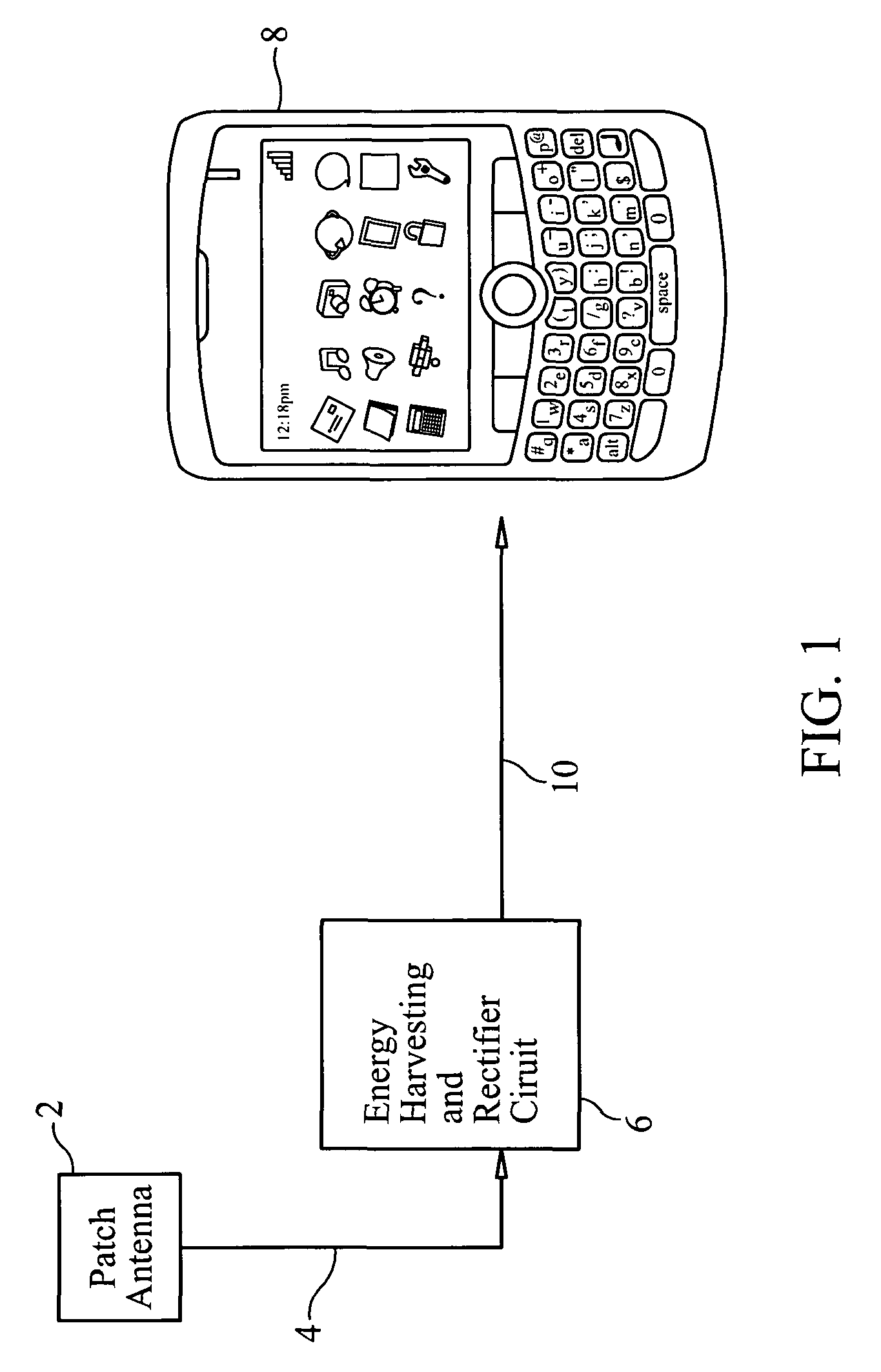
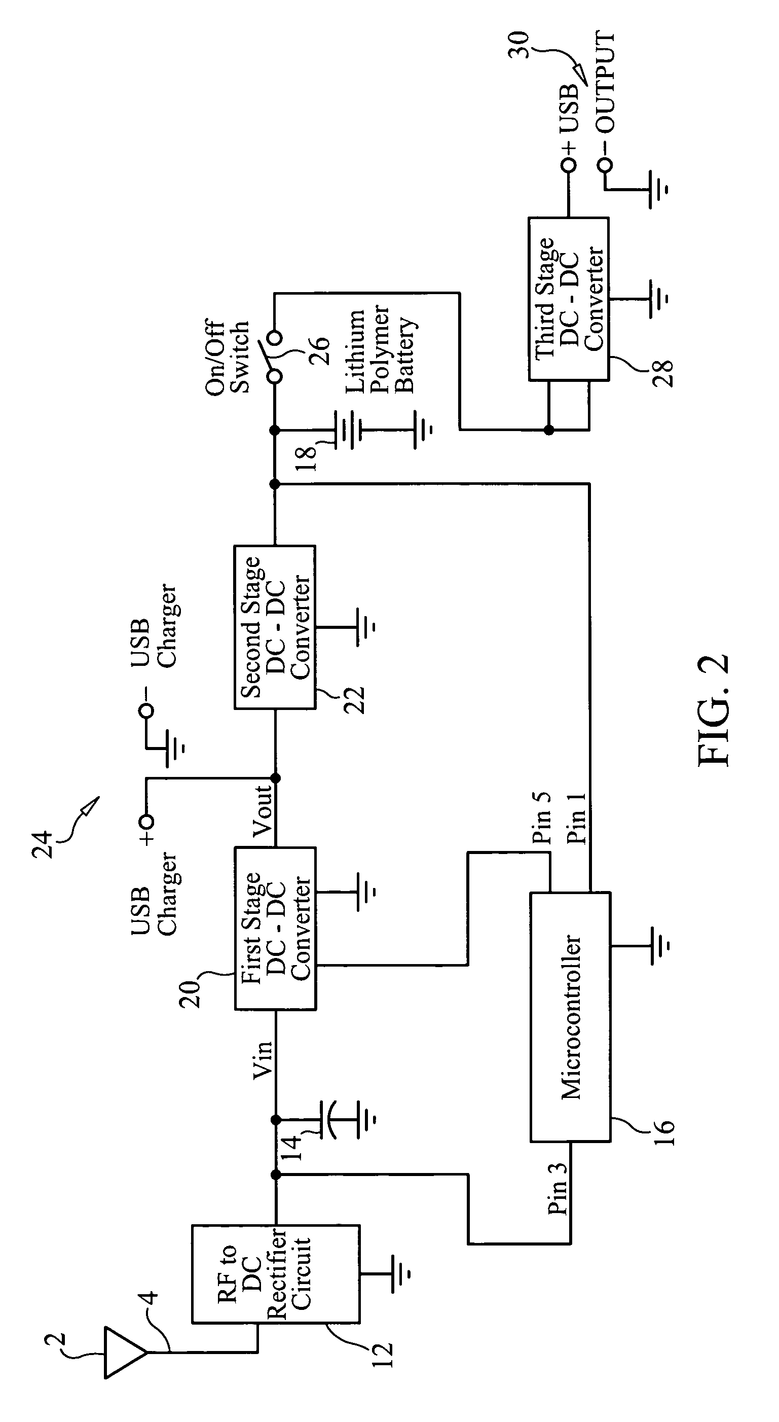
[0028]The present invention is designed to receive radio frequency signals from any WIFI 2.4 to 2.5 GHz source, WiMax, Satellite Radio, Cellular Phone (850 MHz to 900 MHz and 1.8 GHz-1.9 GHz), and UHF TV signals or CATV signals and convert the received radio frequency signal into another form of energy, such as a DC voltage. Even more preferably, the energy harvesting device of the present invention is capable of receiving RF signals from about 500 MHz to about 2.5 GHz, and convert the received signals into electrical energy. The same circuit configuration can also be designed and extended to convert RF signals in VHF, FM and UHF frequencies (such as signals from CATV) into DC electrical energy. This energy is utilized to recharge a battery inside any cell phone through a USB connector. The invention is designed to use WIFI signals, in particular, for energy harvesting because many WIFI signal transmitters are provided and are available in public places, such as airport terminals, c...


PUM

PropertyMeasurementUnit
DC voltageaaaaaaaaaa
voltageaaaaaaaaaa
voltageaaaaaaaaaa

Abstract

An energy harvesting circuit includes one or more broadband or narrow band antennas to detect WIFI (wireless fidelity) or other RF (radio frequency) signals. The signals are rectified and voltage multiplied, and the resultant DC voltage is provided to a power management circuit. The output of the power management circuit charges a lithium battery or other storage device within the energy harvesting circuit. The energy stored in the battery or storage device is provided through a DC / DC converter circuit to a USB output connector to power or recharge the batteries of an external electronic device connected to the USB output connector of the energy harvesting circuit.

Description

CROSS-REFERENCE TO RELATED APPLICATIONS[0001]This application is related to U.S. Provisional Application Ser. No. 61 / 335,459, filed on Jan. 7, 2010, and entitled “Method and Apparatus for Harvesting Energy from WIFI Signals”, U.S. Provisional Application Ser. No. 61 / 402,481, filed on Aug. 31, 2010, and entitled “Method and Apparatus for Harvesting Energy”, and U.S. Provisional Application Ser. No. 61 / 404,290, filed on Sep. 30, 2010, and entitled “Method and Apparatus for Harvesting Energy”, the disclosures of which are incorporated herein by reference and on which by priority is hereby claimed.BACKGROUND OF THE INVENTION[0002]1. Field of the Invention[0003]The present invention relates to energy conservation methods and devices, and more particularly relates to devices which can harvest energy.[0004]2. Description of the Prior Art[0005]Many devices have been proposed or implemented which harvest energy from different types of naturally-occurring energy sources. These energy sources ...

Claims


Application Information

Patent Timeline
Patent Type & Authority Patents(United States)
IPC IPC(8): H01M10/46H01M10/44H02J7/00
CPCH02J17/00H02J7/35H02J2007/0062H02J50/001H02J50/30H02J50/27H02J50/402H02J50/20H02J7/00
Inventor TINAPHONG, PRAPAN PAUL
Owner VOXX INTERNATIONAL
Learn More