Liquid ejecting apparatus

a technology of liquid ejecting apparatus and nozzle, which is applied in printing and other directions, can solve the problems of air bubbles clogging the ink flow channel or nozzle, difficult to completely prevent entrainment, and missing dots, etc., and achieves the effect of improving the discharge of air bubbles

Active Publication Date: 2013-02-12
SEIKO EPSON CORP
View PDF7 Cites 6 Cited by
  • Summary
  • Abstract
  • Description
  • Claims
  • Application Information

AI Technical Summary

Benefits of technology

[0012]An advantage of some aspects of the invention is that a liquid ejecting apparatus capable of improving the discharge of air bubbles is provided.
[0014]Accordingly, since the liquid ejecting apparatus has a configuration in which the pressure adjustment unit having the pressure adjustment valve is provided between the filter chamber and the liquid ejecting head, the opening size of the filter hole is set to ½ of the minimum inner diameter of the nozzle or lower, and the pressure for pumping liquid with the pressurizing unit is adjusted to the value that permits air bubbles in the upstream side space to pass through the filter, the air bubbles in the upstream side space are divided into smaller air bubbles when passing through the filter and the air bubble can be a size smaller than the minimum inner diameter of the nozzle even after depressurized in the pressure adjustment unit. Therefore, the air bubbles are discharged with ink from nozzles to the outside of the ink ejecting head without clogging the nozzles when ink is ejected through nozzles of the ink ejecting head. This makes it possible to prevent the air bubbles from being stagnated in the flow channel from the liquid containing member to the nozzles of the liquid ejecting head without a cleaning operation which has been performed in the related art. Since a cleaning operation is not needed, time and ink consumption for the cleaning operation can be saved.

Problems solved by technology

Although various measures are taken in this type of printer to prevent the entrainment of air bubbles, it is difficult to completely prevent the entrainment.
When some of the air bubbles which have excessively increased in size move with the ink flow toward a pressure chamber, the air bubbles may clog the ink flow channel or nozzle.
This may cause so-called missing dots in which ink is not ejected from the nozzle.
This may cause air bubbles to clog a nozzle, resulting in a problem of so-called missing dots in which ink is not properly ejected.
In addition, the cleaning process has another problem in that an extra amount of ink is consumed.
The above-mentioned problems exist not only in ink jet recording apparatuses having a recording head that ejects ink, but also in other liquid ejecting apparatuses in which a filter chamber having a filter therein is provided partway along the liquid supply path.

Method used


Image

  • Liquid ejecting apparatus
  • Liquid ejecting apparatus
  • Liquid ejecting apparatus

Examples


Embodiment Construction

[0027]Embodiments of the invention will be described below with reference to the accompanying drawings. Although the embodiments are specifically explained as preferred examples of the invention, the scope of the invention is not limited to those embodiments described herein except as specifically limited in the description. In the following description, an ink jet recording apparatus (hereinafter referred to as a printer) will be described as an example of the liquid ejecting apparatus of the invention.

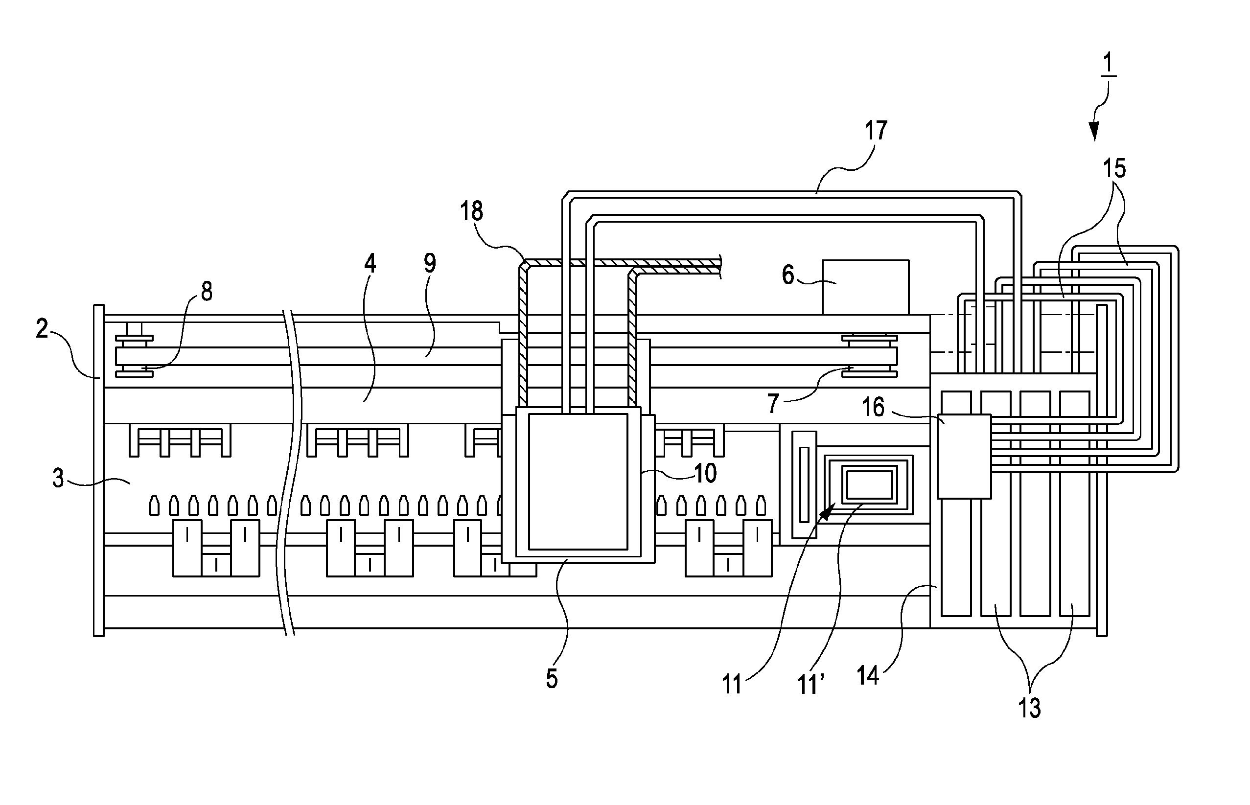
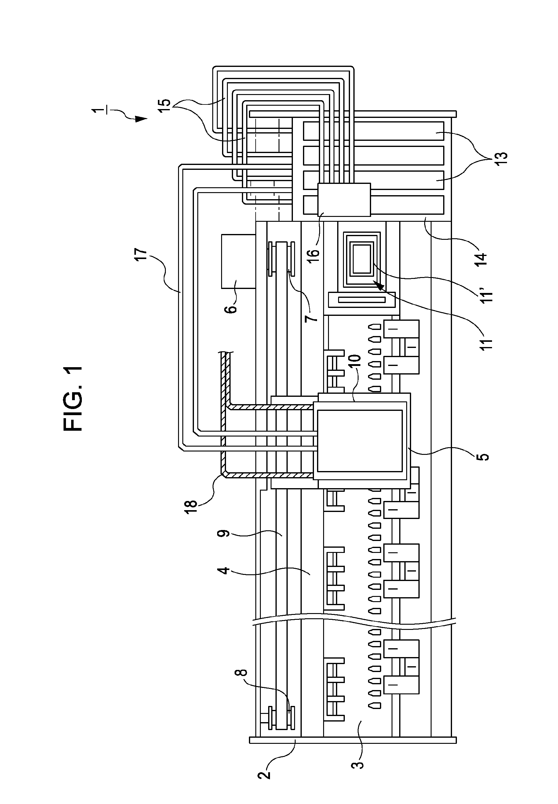
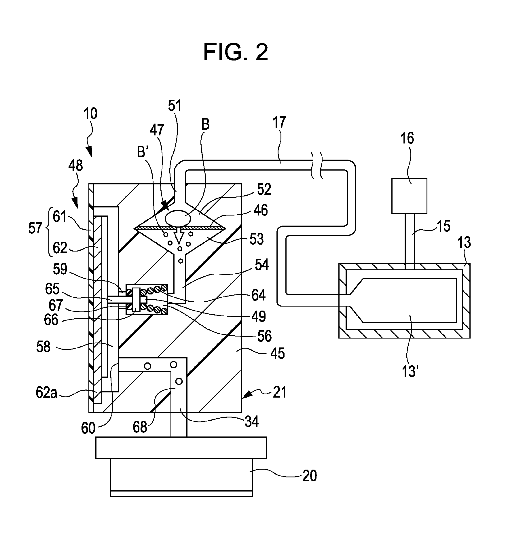
[0028]FIG. 1 is a plan view showing a configuration of a printer 1 in which an ink ejecting unit 10 (FIG. 2) is mounted. FIG. 2 is a schematic view showing a configuration of a path extending from an ink cartridge 13 to a recording head 20 via a pressure adjustment unit 21. The printer 1 according to this embodiment is an apparatus that performs recording of images or the like by ejecting ink in a liquid form (which corresponds to liquid of the invention) toward the surface of a reco...


PUM


Abstract

A liquid ejecting apparatus in which a pressure adjustment unit having a pressure adjustment valve is provided between a filter chamber that houses a filter and a recording head having nozzles through which ink is ejected, the opening size of filter hole is set to ½ of a minimum inner diameter Da of the nozzle of the recording head or lower, and a pressure for pumping ink with an air pump is adjusted to a value that permits air bubbles in the upstream side space to pass through the filter.

Description

[0001]The entire disclosure of Japanese Patent Application No: 2010-181088, filed Aug. 12, 2010 are expressly incorporated by reference herein.BACKGROUND[0002]1. Technical Field[0003]The present invention relates to liquid ejecting apparatuses such as an ink jet recording apparatus, and more specifically, liquid ejecting apparatuses having a filter that filters liquid to be supplied to a liquid ejecting head and a filter chamber that houses the filter.[0004]2. Related Art[0005]Typical example of liquid ejecting apparatuses having a liquid ejecting head capable of ejecting a liquid and configured to eject a variety of liquids from the liquid ejecting head include, for example, an image recording apparatus such as an ink jet printer that performs recording by ejecting ink droplets so as to cause the ink droplets to land on a landing target (recording medium) such as a recording sheet. Further, in recent years, such a liquid ejecting apparatus has been applied not only to image recordi...

Claims


Application Information

Patent Timeline
Patent Type & Authority Patents(United States)
IPC IPC(8): B41J2/175B41J2/19
CPCB41J2/17509B41J2/17563B41J2/17596
Inventor YOKOUCHI, HIDEYA
Owner SEIKO EPSON CORP
Why Eureka
Try Eureka