
Card connector

a card connector and connector technology, applied in the direction of coupling device connection, coupling/disconnecting parts, instruments, etc., can solve the problem and achieve the effect of small card connector width and small siz

Inactive Publication Date: 2013-02-12
CHENG UEI PRECISION IND CO LTD
View PDF6 Cites 48 Cited by
  • Summary
  • Abstract
  • Description
  • Claims
  • Application Information

AI Technical Summary

Benefits of technology

The present invention provides a new ejection mechanism for a card connector that allows for a smaller size. This mechanism includes a pushing shaft, plural balls, a sliding bulk, and a pressing element. By using this design, the width of the card connector can be significantly reduced, making it more compact and easier to use.

Problems solved by technology

However, the ejection mechanism of the conventional card connector occupies a large space in the width direction, and it is a disadvantage to make the card connector to be of a small size.

Method used


Image

  • Card connector
  • Card connector
  • Card connector

Examples


Embodiment Construction

[0012]In order to illustrate the techniques, structural features, achieved objectives and effects of the present invention in details, embodiments are provided in conjunction with drawings and are described as follows.

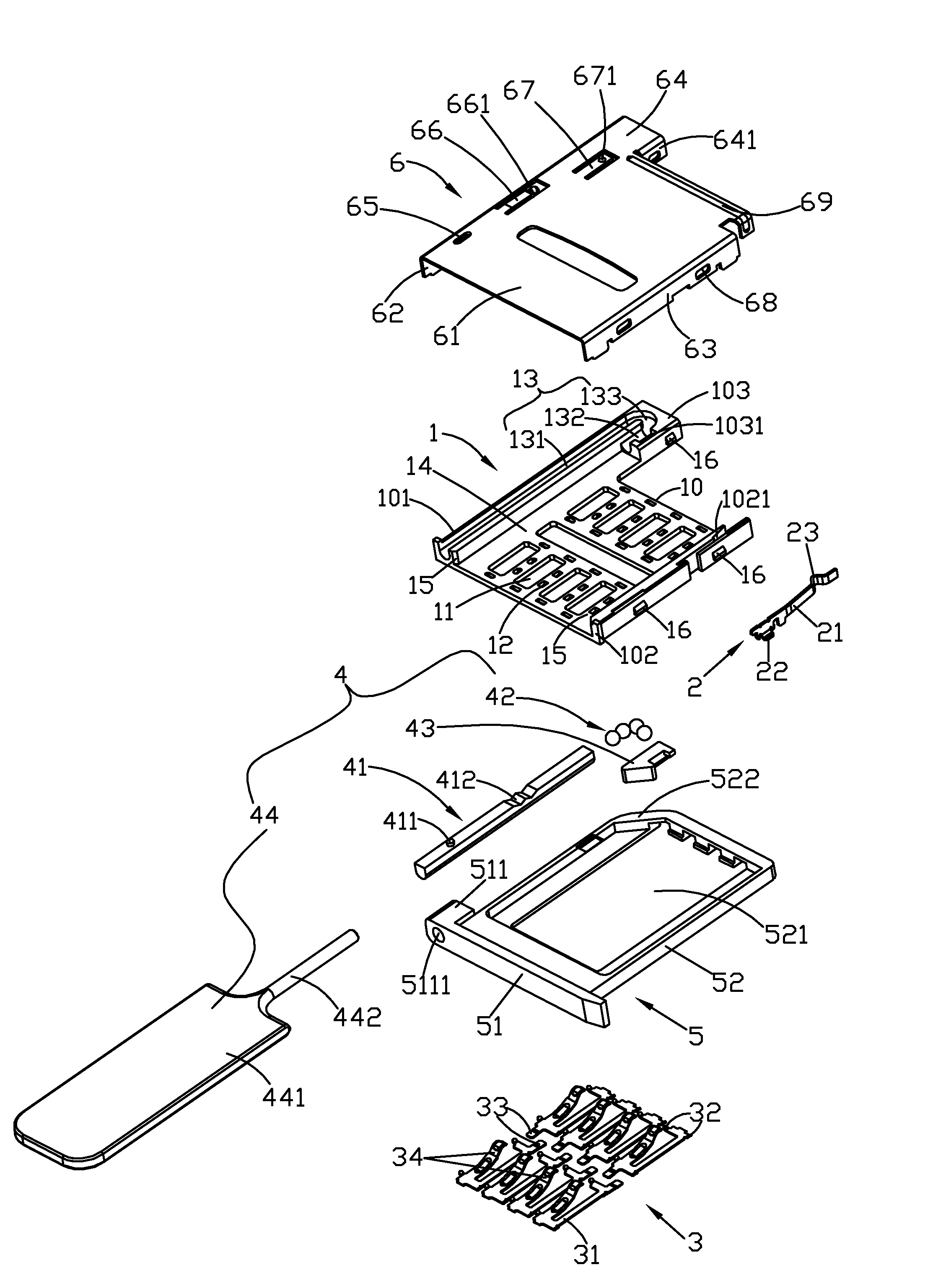
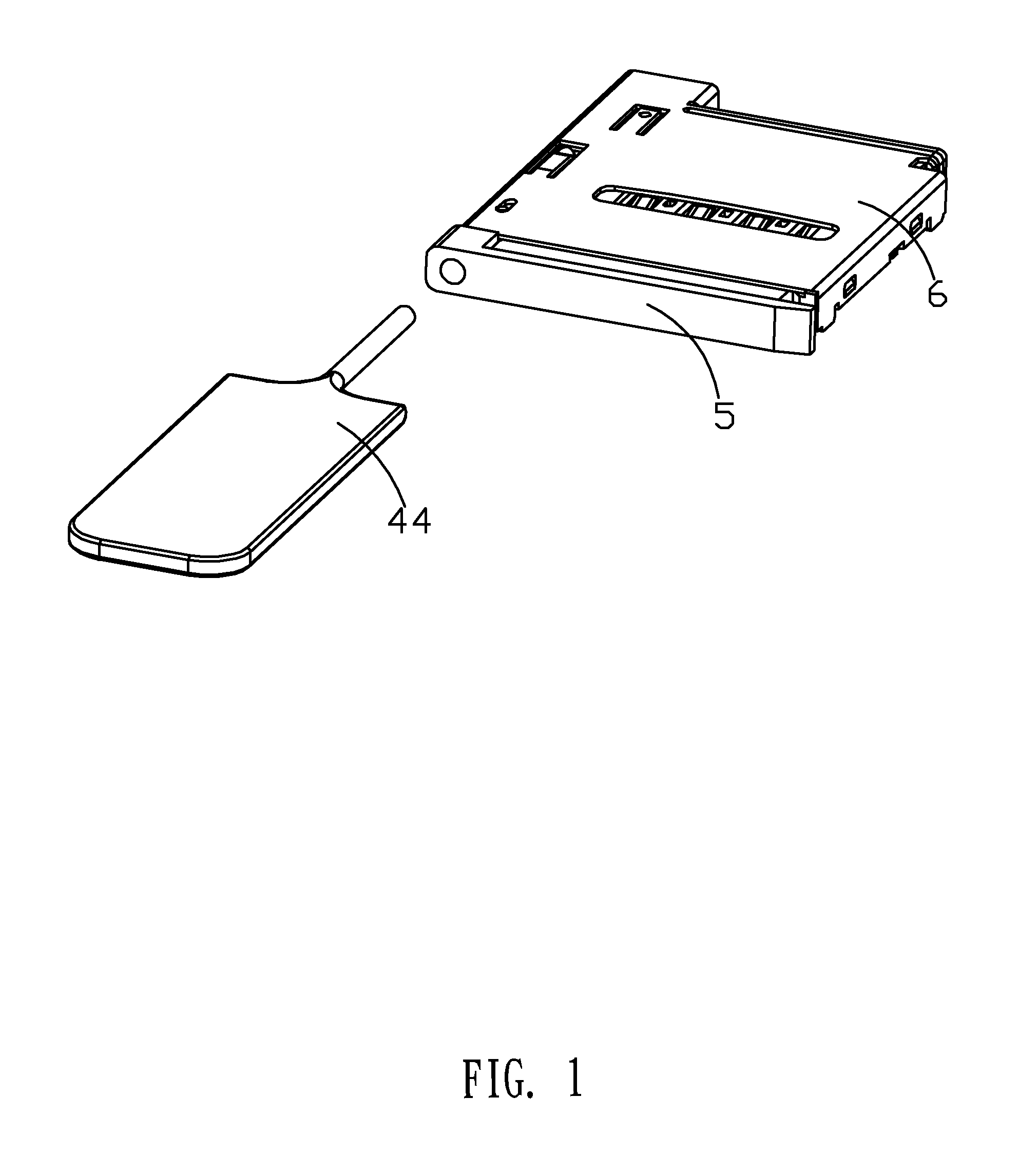
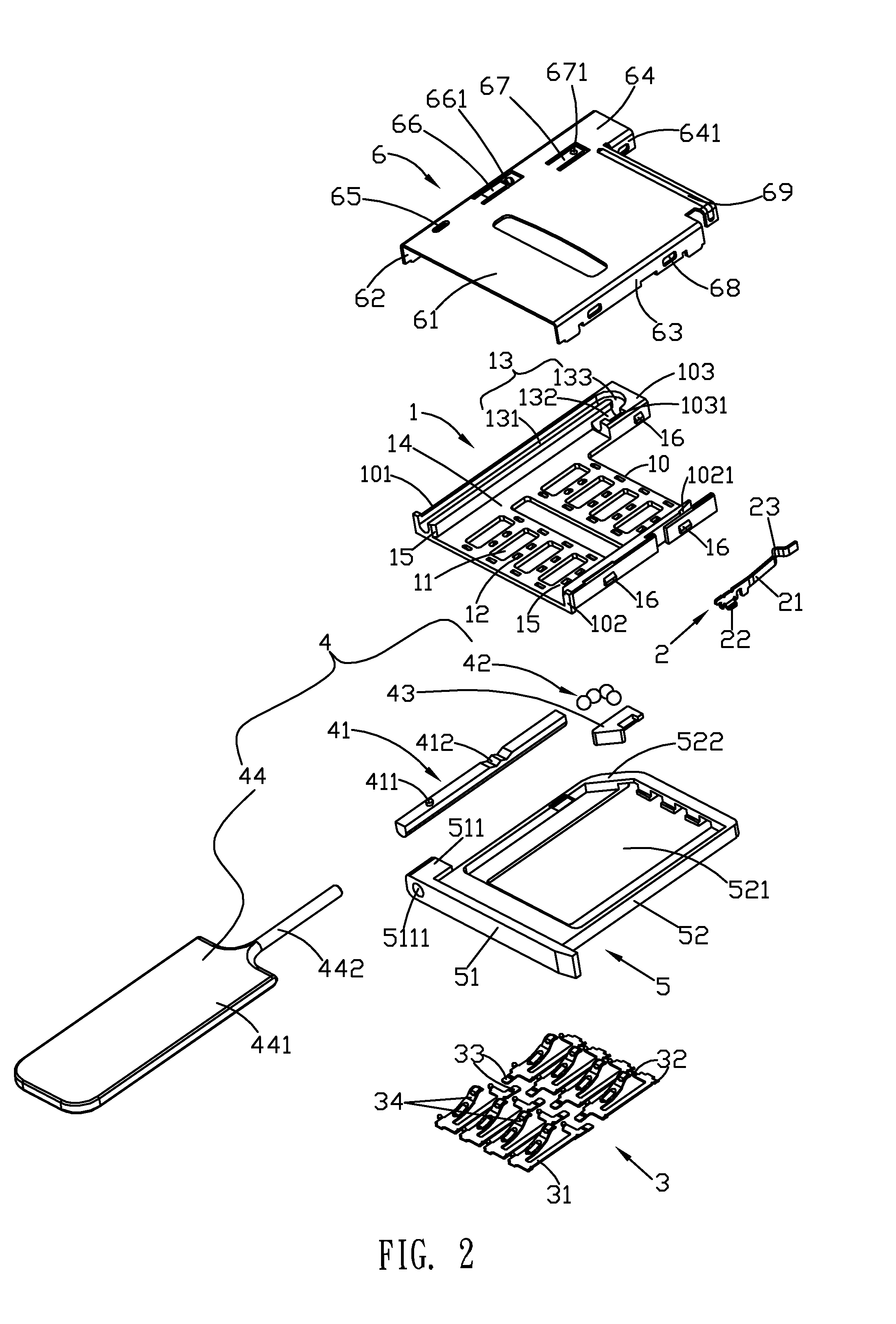
[0013]Referring to FIG. 1 and FIG. 2, the card connector of the present invention comprises an insulating body 1, a detecting terminal 2, a plurality of conductive terminals 3, an ejection mechanism 4, a tray 5, and a metal shell 6.

[0014]Referring to FIG. 2, the insulating body 1 has a substrate 10. The substrate 10 is perforated to form a plurality of terminal slots 11 and is impressed to form a plurality of pin holes 12 around each terminal slot 11. The left side, right side, and left part of the rear side of the substrate 10 are extended upward to form a left stand 101, a right stand 102, and a rear stand 103, respectively. The substrate 10, the left stand 101, the right stand 102, and the rear stand 103 form an accommodating trough 14. The top surfaces of the left ...


PUM


Abstract

The present invention discloses a card connector which comprises an insulating body, a plurality of conductive terminals, an ejection mechanism, a tray, and a metal shell. The insulating body has a substrate. One side of the substrate is perforated to form a guide groove of which a bottom surface is a cylindrical surface. The ejection mechanism comprises a pushing shaft, a plurality of balls, a sliding bulk, and a pressing element. The pushing shaft, the plural balls, and the sliding bulk are slidably disposed in the guide groove. The plural balls are located between the pushing shaft and the sliding bulk and can be rolled sequentially. By the design of the ejection mechanism constructed by the pushing shaft, the plural balls, the sliding bulk, and the pressing element, the present invention has an advantage of making the card connector to be of a small size.

Description

TECHNICAL FIELD OF THE INVENTION[0001]The present invention relates to a connector, and more particularly, to a card connector able to be implemented as a small size.BACKGROUND OF THE INVENTION[0002]Electronic cards have been widely used in electronic products such as digital cameras, notebooks, and etc., for expanding memory storage and solving the existed problem of memory shortage. As living quality is improved, the demands for minimizing the size of the electronic products are higher and higher. Therefore, electronic product designers have to provide creative designs and improve the products again and again. They should put efforts to make the electronic products to be of a small size. A conventional card connector usually comprises an insulating body, a plurality of conductive terminals, a metal shell, and an ejection mechanism. The ejection mechanism is generally constructed by an elastic element, a sliding bulk, and a guide rod for achieving card insertion and card ejection.[...

Claims


Application Information

Patent Timeline
Patent Type & Authority Patents(United States)
IPC IPC(8): H01R13/62
CPCG06K13/0862G06K13/0806
Inventor SU, YU-HUNGCHENG, YA-YUN
Owner CHENG UEI PRECISION IND CO LTD
Features
  • Generate Ideas
  • Intellectual Property
  • Life Sciences
  • Materials
  • Tech Scout
  • Unparalleled Data Quality
  • Higher Quality Content
  • 60% Fewer Hallucinations
Learn More