Landing gear

a technology of landing gear and gear, which is applied in the direction of landing gear, aircraft components, aircraft control, etc., can solve the problems of eddy current(s), turbulent air flow that generates extra noise, and flow being created, so as to reduce disruption or inconvenience, and the effect of minimizing the noise generated by aircra

Inactive Publication Date: 2013-02-19
AIRBUS OPERATIONS LTD
View PDF16 Cites 4 Cited by
  • Summary
  • Abstract
  • Description
  • Claims
  • Application Information

AI Technical Summary

Benefits of technology

[0004]It is an aim of the present invention to provide a landing gear that generates less noise compared to a landing gear of the same size that has not been adapted, designed or manufactured in accordance with the present invention. An additional, or alternative, aim of the present invention is to provide an improved noise reduction element for use on an aircraft landing gear.
[0005]According to one aspect of the invention there is provided an aircraft landing gear including a noise-reducing element that includes an air-deflecting surface and an airflow-reducing region through which, in use, air may pass, whereby the noise-reducing element is able in use to deflect air away from a noise-generating region of the landing gear, whilst allowing some air to pass through the element, thereby reducing the noise caused by the passing of the landing gear through the air.
[0006]Thus noise caused by the interaction of the air and the landing gear caused during the approach when landing may be reduced by means of providing a noise-reducing element according to the present invention. The provision of an airflow-reducing region enables the noise-reducing effect of the noise-reducing element to be improved. Exactly how the provision of such an airflow-reducing region reduces noise has not been fully analysed, although a possible explanation relating to the reduction of the production of turbulent airflows is provided below.

Problems solved by technology

Deflecting air away from these parts reduces noise generated by such parts, but can result in separate air flows being created that converge downstream of the landing gear.
The converging air flows interact with each other, possibly resulting in turbulent air flows that generate extra noise.
Also, the provision of an element that deflects air, may have a shape that results in eddy current(s) and further turbulence being created immediately upstream of the element.

Method used


Image

  • Landing gear
  • Landing gear
  • Landing gear

Examples


first embodiment

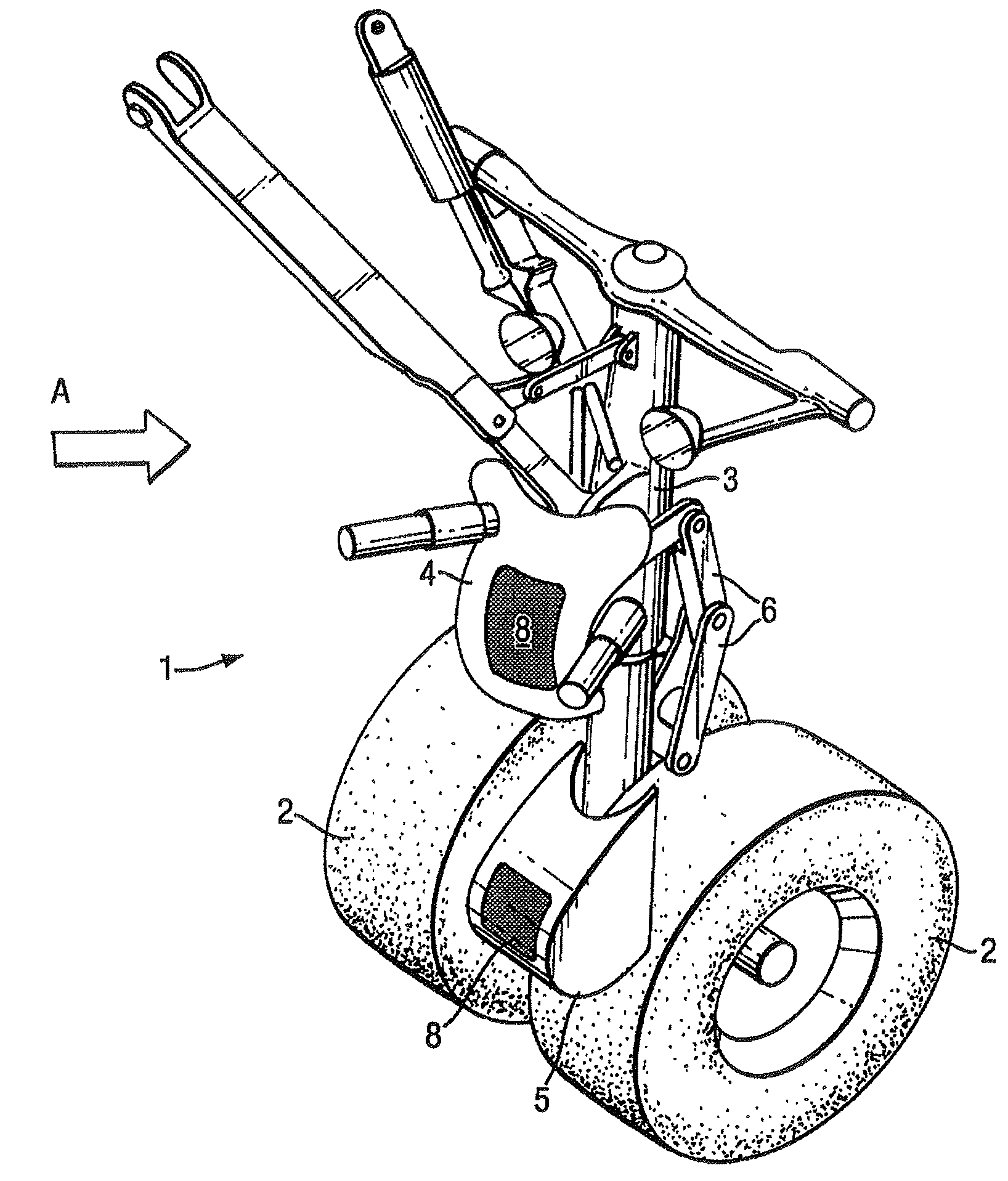
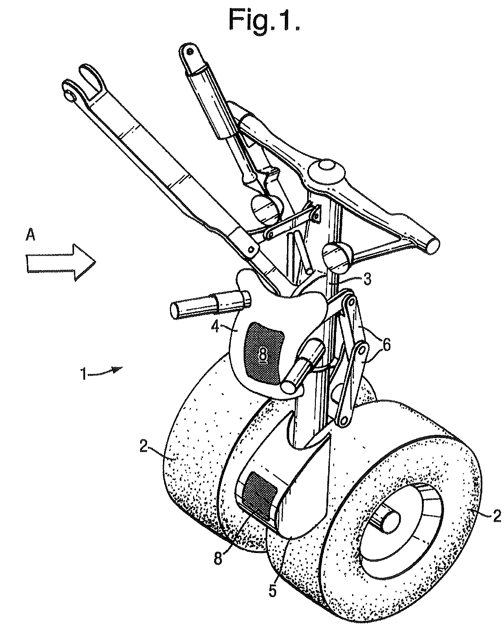
[0054]FIG. 1 illustrates the invention concerning a nose landing gear 1. The nose landing gear 1 includes wheels 2 a central support column 3 (or leg) and an upper fairing 4 and a lower fairing 5. The nose gear 1 is shown in its deployed position during landing of an aircraft (not shown in FIG. 1) to which the nose landing gear 1 is attached. The direction of flow of air relative to the nose gear is indicated by arrow A which points to the right in FIG. 1, since the nose gear and aircraft are moving to the left.

[0055]The upper fairing 4 is positioned over the central support column 3 in a position that shields parts 6 of the landing structure that are associated with the steering of the nose gear wheels 2. The parts 6 that are shielded by the fairing include steering actuators (comprising rods, linkages and the like) that would if not shielded generate significant noise. The upper fairing 4 is attached to the gear 1 via steering actuator mounting brackets. The upper fairing 4 has re...

second embodiment

[0066]the invention is shown in FIG. 3, which shows a main landing gear 11 including wheels 2 and a central support column 3 (or leg). The gear 11 includes several fairings 12, 13, 14, 15. The main gear 11 is shown in its deployed position during landing of an aircraft (not shown in FIG. 3) to which the main landing gear 11 is attached. The direction of flow of air relative to the landing gear is indicated by arrow B which points to the left in FIG. 3, since the main landing gear and aircraft are moving to the right.

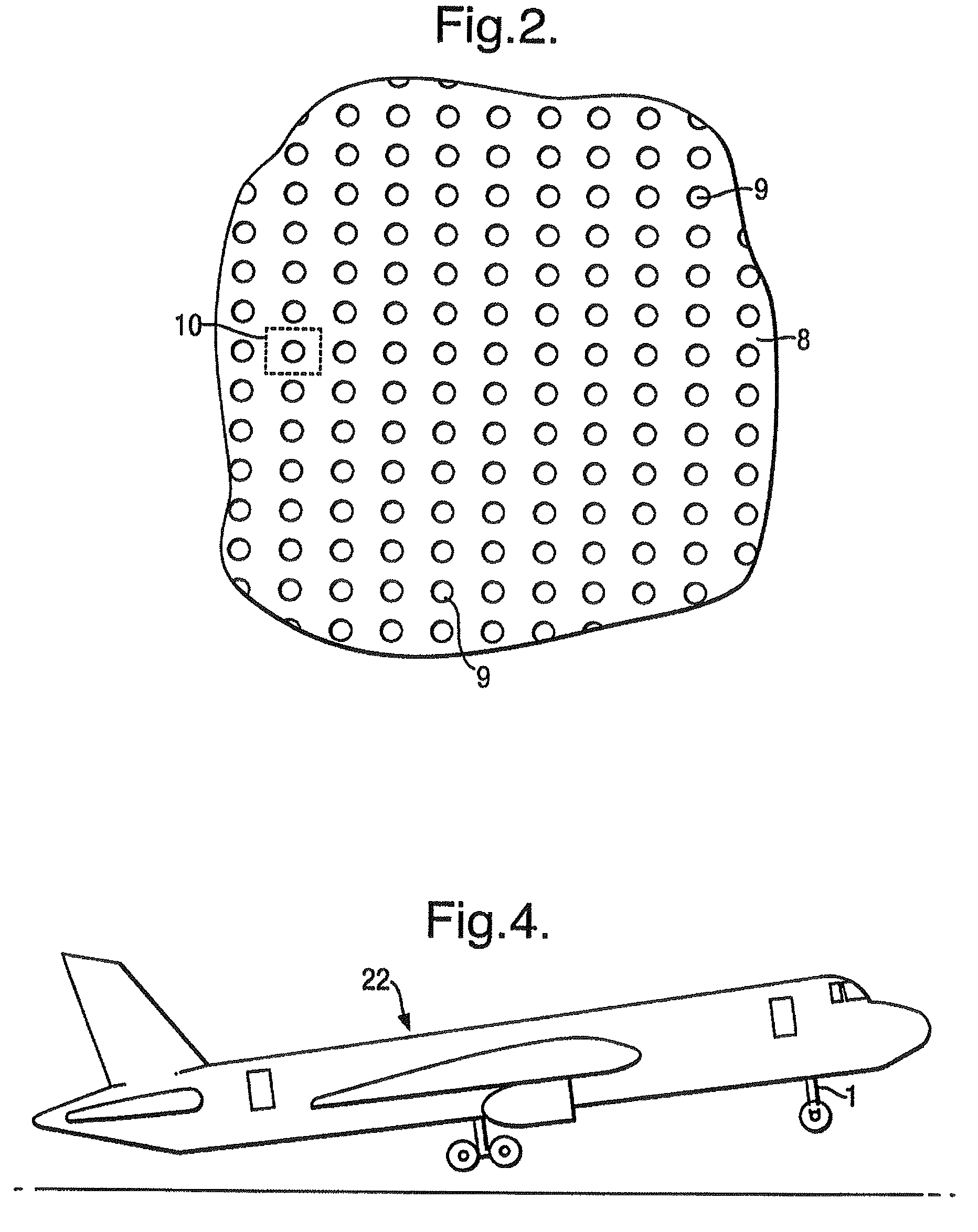
[0067]The fairings illustrated in FIG. 3 include an undertray fairing 12, an articulation-link fairing 13, a door / dragstay-closure fairing 14 and an upper side-stay fairing 15. Each fairing includes, in a manner similar to that of the fairings shown in FIG. 1, a perforated region 8 which covers a stagnation point or part of a stagnation line. Thus the principles behind and improvements provided by the arrangement of the fairings shown in FIG. 3 and the perforated regions...

fourth embodiment

[0114]In this fourth embodiment the noise-reducing mesh 212 is made from uncoated stainless steel, but other metals are suitable, such as brass, titanium or aluminium or alloys thereof. The mesh may alternatively be made from plastic, such as Nylon, or from composite material. The wire may be coated with a protective coating, such as a powder coating or paint. The use of a coating may also enable the porosity of the mesh to be reduced, by increasing the effective thickness of the wire. The mesh 212 is pre-formed to ensure a close fit to the support structure 214.

[0115]The gap size in the mesh 212 at its widest is about 5 mm, but in some regions the gap size is as low as 1 mm. Other gap sizes might also provide noise-reduction benefits. Gap sizes in the range of 0.1 mm to 2 mm would be preferable. The gap may however be 10 mm or larger. The gap sizes may be in the range of 0.2 mm to 12.5 mm. The gap size need not be uniform across the mesh 212. It may for example be preferable to hav...


PUM


Abstract

An aircraft landing gear is described including a noise-reducing means. In one embodiment there is a noise-reducing element that includes an air-deflecting surface, in the form of a fairing, and a perforated airflow-reducing region. In use, some air passes through the perforations, while other air is deflected by the fairing away from a noise-generating region of the landing gear. Noise caused by the passing of the landing gear through the air is therefore reduced. In another embodiment a noise-reducing layer in the form of a mesh is supported by a skeleton structure.

Description

RELATED APPLICATIONS[0001]The present application is a Continuation-in-Part of U.S. application Ser. No. 10 / 533,376 filed Apr. 29, 2005, which is a national phase entry of International Patent Application No. PCT / GB2003 / 004586, which was filed on Oct. 23, 2003 and which claims priority from United Kingdom Application Number 0225517.2, filed Nov. 1, 2002. The present application also claims priority from UK Patent Application No. 0720978.6 filed on Oct. 26, 2007. The disclosures of each of the aforementioned patent applications are hereby incorporated by reference herein in their entirety.BACKGROUND OF THE INVENTION[0002]The present invention relates to landing gear and to noise-reduction apparatus for use on an aircraft. More particularly, but not exclusively, the invention relates to landing gear designed to reduce the noise generated by the interaction of the landing gear and the air flowing past it during flight, take-off and / or landing. Such noise-reduction may be achieved by me...

Claims


Application Information

Patent Timeline
Patent Type & Authority Patents(United States)
IPC IPC(8): B64C1/40
CPCB64C7/00B64C25/16B64C2025/003
Inventor CHOW, LEUNG CHOIWOOD, CHRISTOPHER NEILCAMPBELL, PHILIP
Owner AIRBUS OPERATIONS LTD
Why Eureka
Try Eureka