Check patentability & draft patents in minutes with Patsnap Eureka AI!

Vacuum attachment for the collection of liquids

a vacuum cleaner and liquid technology, applied in the field of vacuum cleaner attachments, can solve the problems of difficult cleaning up wet spills, inconvenient methods for removing solids such as scrubbing or scraping, and inconvenient methods for removing solids such as absorption

Inactive Publication Date: 2013-02-26
GROTTODDEN JOHN P
View PDF22 Cites 1 Cited by
  • Summary
  • Abstract
  • Description
  • Claims
  • Application Information

AI Technical Summary

Benefits of technology

The single-part design enables cost-effective, portable, and reliable liquid separation and storage, preventing contamination of the vacuum cleaner and allowing for quick disposal of collected liquids, with the optional filter enhancing prevention of water droplets from entering the hose.

Problems solved by technology

It is difficult cleaning up wet spills, especially on carpet or upholstery.
Methods for collecting solids like scrubbing or scraping are not suitable for removing moisture.
Methods for removing moisture like absorption are not suitable for removing solids.
Although the liquid separators of the above cited references allow the vacuum unit to remove liquid, the attachments tend to be bulky and stationary, limiting the useful range of the vacuum cleaner.
a. They require the assembly of multiple components or the joining of 2 molded halves. Assembly is an extra step in the manufacturing process, making them more expensive to produce.
b. Assembly of the attachment as separate components requires thick material so that is holds its shape to that is can be fastened together.
c. Assembly also introduces tolerance problems in manufacturing, not present in a single-part design.
If an attachment comprised of multiple components is dropped or is stored at a high temperature, causing deformation, it is more likely to fail in function or to leak than a single-part design.
They lack a filter to further prevent water droplets from the air stream to enter the vacuum hose.

Method used


Image

  • Vacuum attachment for the collection of liquids
  • Vacuum attachment for the collection of liquids
  • Vacuum attachment for the collection of liquids

Examples


embodiment

Preferred Embodiment

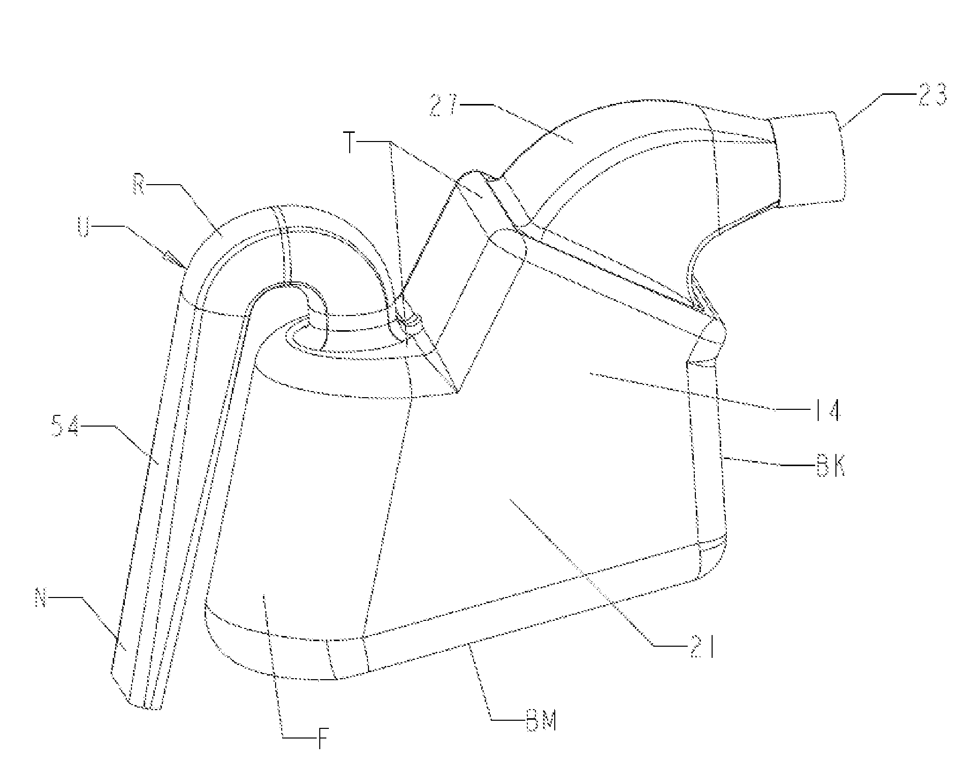
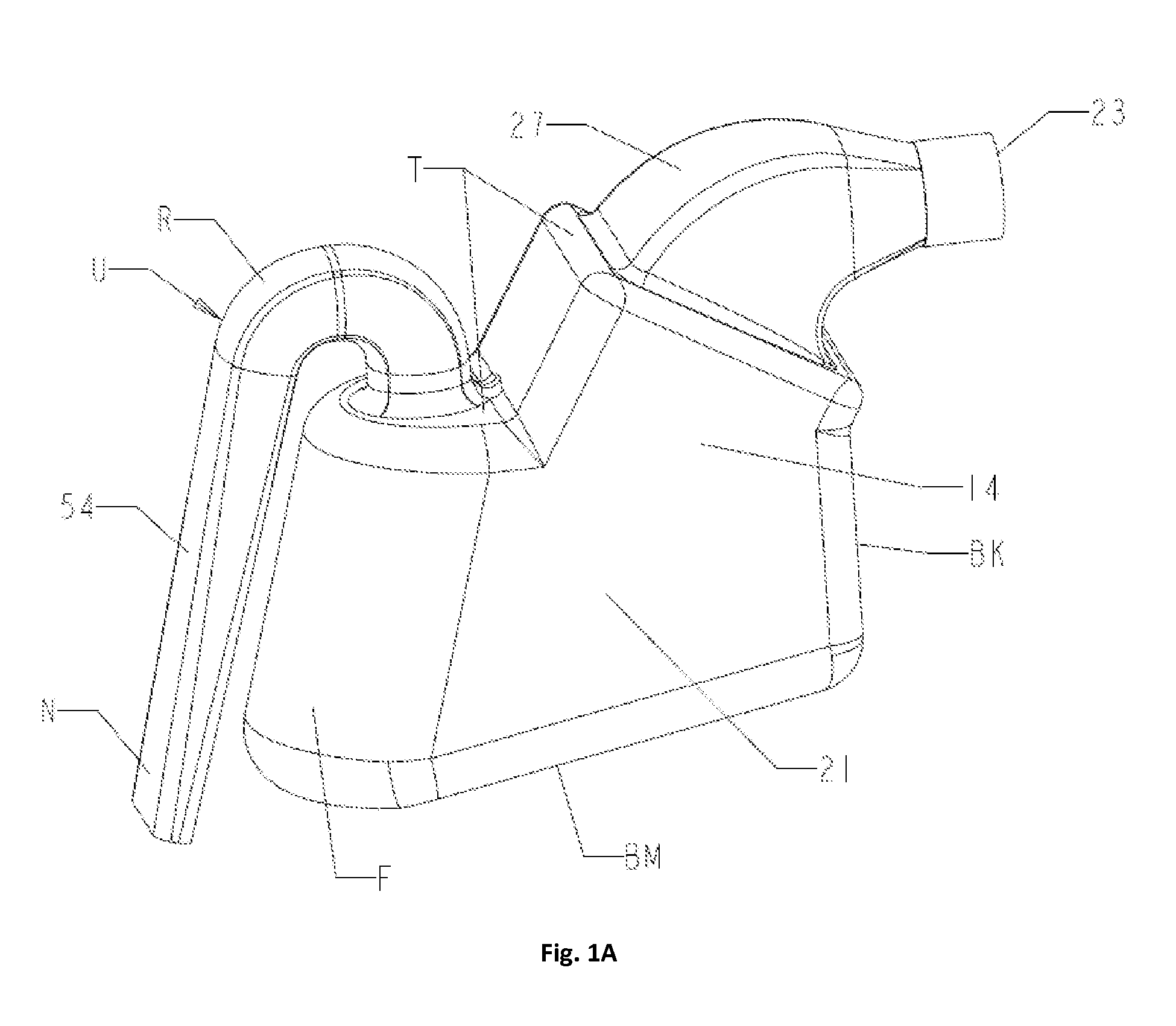
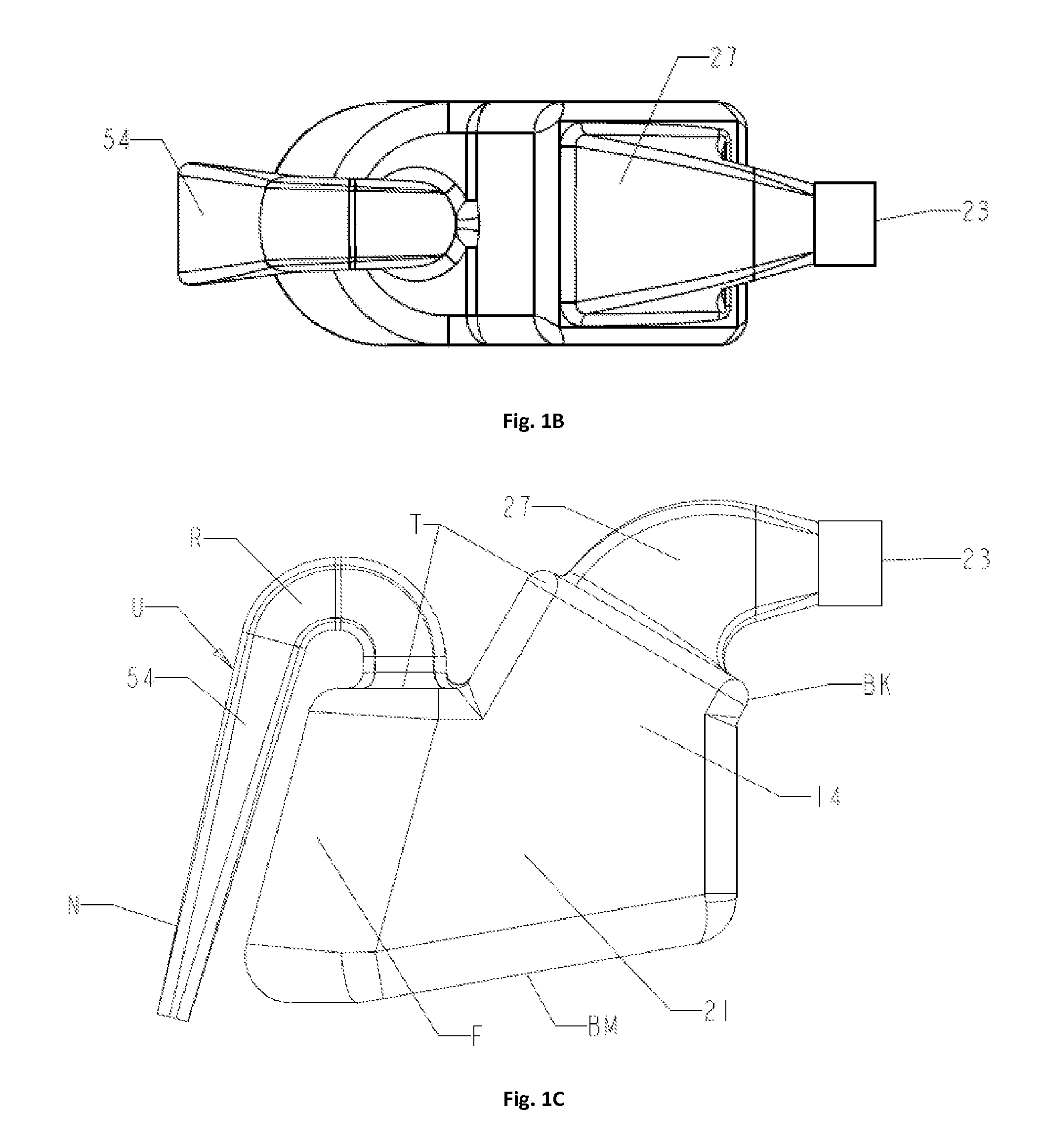
[0048]As shown in FIG. 1A-C, the Vacuum Attachment for the Collection of Liquids comprises a reservoir 21, suction port 23, suction passage 27 and an inlet nozzle 54. Preferably, the attachment is manufactured as a single-part by a process such as blow molding. While described further later, FIGS. 2C and 3C show a cross section view of embodiments of the attachment that depict a wall structure of the single-part construction that forms the reservoir 21, suction port 23, suction passage 27, and inlet nozzle 54 and the pathway or mechanism through which liquid is removed (from the air) before reaching the suction port 23. The attachment may be composed of a transparent or translucent plastic, enabling the user to see the liquid level in the reservoir 21.

[0049]The suction port 23, is designed to receive a standard 11 / 4″ vacuum hose. It is located on the top (T) of the attachment because gravity will pull any liquid in the attachment to the bottom (BM). Having the su...


PUM


Abstract

The invention provides a wet vacuum attachment, connecting to a hose of a commercially available vacuum cleaner that separates a liquid from a suction airstream created by the vacuum, so that the liquid does not enter the vacuum cleaner intake hose. The attachment can be manufactured as a single-part, having a suction port where the vacuum hose is attached, a suction passage to communicate with a reservoir in a region of low velocity for the separation and storage of the collected liquid, an inlet nozzle to increase the airstream velocity and to engage the working surface. In an additional embodiment, a filter media is inserted into a filter housing located in the region of low velocity between the suction passage and the reservoir to further prevent liquid from entering the vacuum hose.

Description

BACKGROUND OF THE INVENTION[0001]1. Field of Invention[0002]This invention relates to a vacuum cleaner attachment that can pick up a liquid spill, while preventing the liquid from being drawn into the hose of the vacuum unit.[0003]2. Related Art[0004]It is difficult cleaning up wet spills, especially on carpet or upholstery. Methods for collecting solids like scrubbing or scraping are not suitable for removing moisture. Methods for removing moisture like absorption are not suitable for removing solids. Suction is the best method to accommodate the removal of both solids and liquid.[0005]Inventors have created vacuums suitable for the collection and storage of wet solids and liquids. Several types of attachments have been invented which do not have their own suction motor.[0006]The following attachments are comprised of multiple components, mainly having inlet and outlet pipes, and a reservoir which separates from a cover. [0008] U.S. Pat. No. 4,179,769 to Lundquist (1979), [0009] U....

Claims


Application Information

Patent Timeline
Patent Type & Authority Patents(United States)
IPC IPC(8): A47L5/00A47L7/00A47L9/00A47L9/10A47L9/20A47L9/02A47L9/04A47L9/06
CPCA47L7/0014A47L9/02A47L9/10A47L9/248
Inventor GROTTODDEN, JOHN P.
Owner GROTTODDEN JOHN P
Features
  • R&D
  • Intellectual Property
  • Life Sciences
  • Materials
  • Tech Scout
  • Unparalleled Data Quality
  • Higher Quality Content
  • 60% Fewer Hallucinations
Learn More