
Dual conversion transmitter with single local oscillator

a transmitter and local oscillator technology, applied in the field of transmitters and/or transceivers, can solve the problems of unnecessarily high material cost, difficult design with adequate phase noise, and difficult filtering of unwanted signals, and achieve the effect of facilitating frequency conversion and facilitating frequency conversion

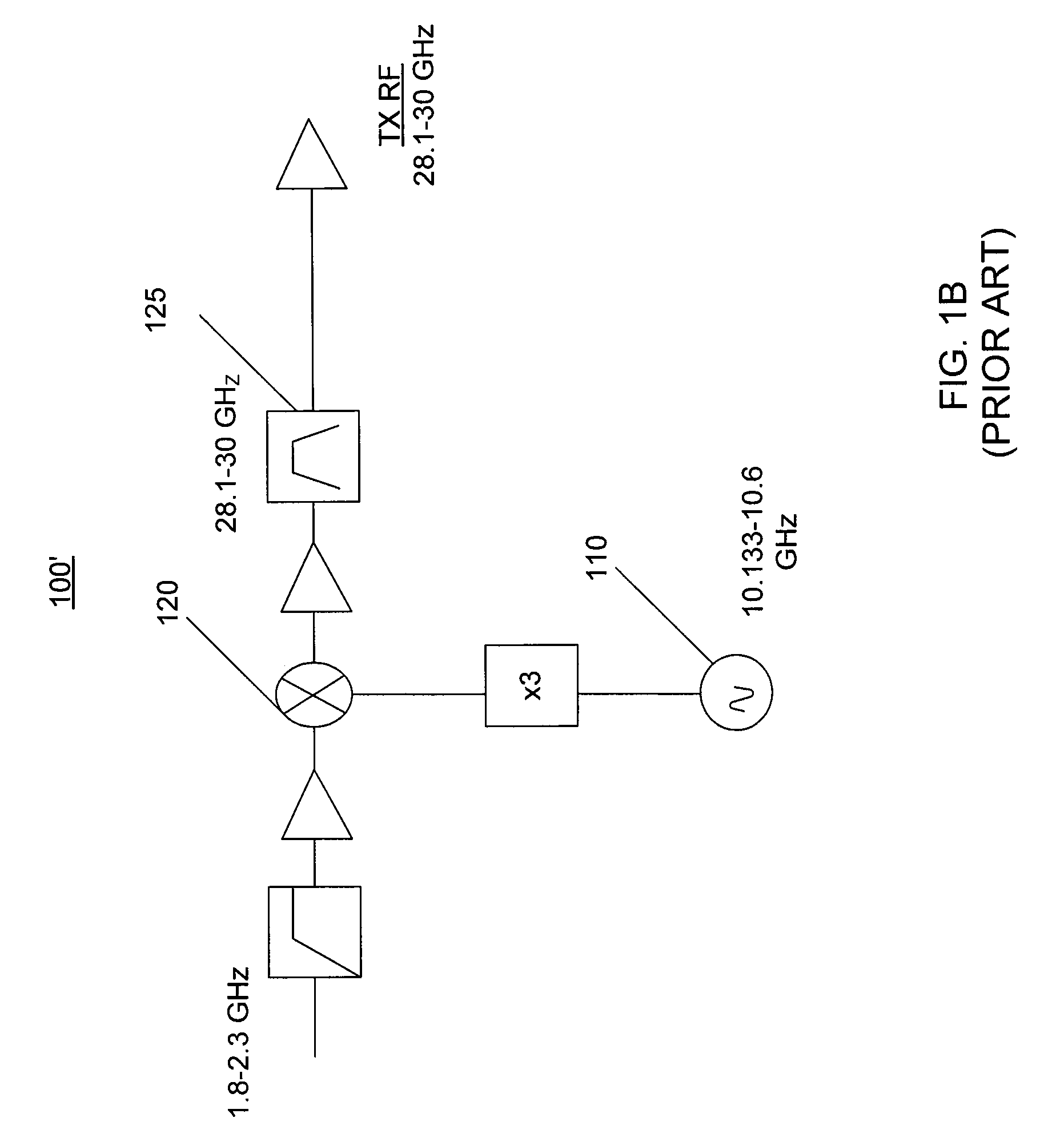
Active Publication Date: 2013-02-26
VIASAT INC
View PDF35 Cites 36 Cited by
  • Summary
  • Abstract
  • Description
  • Claims
  • Application Information

AI Technical Summary

Problems solved by technology

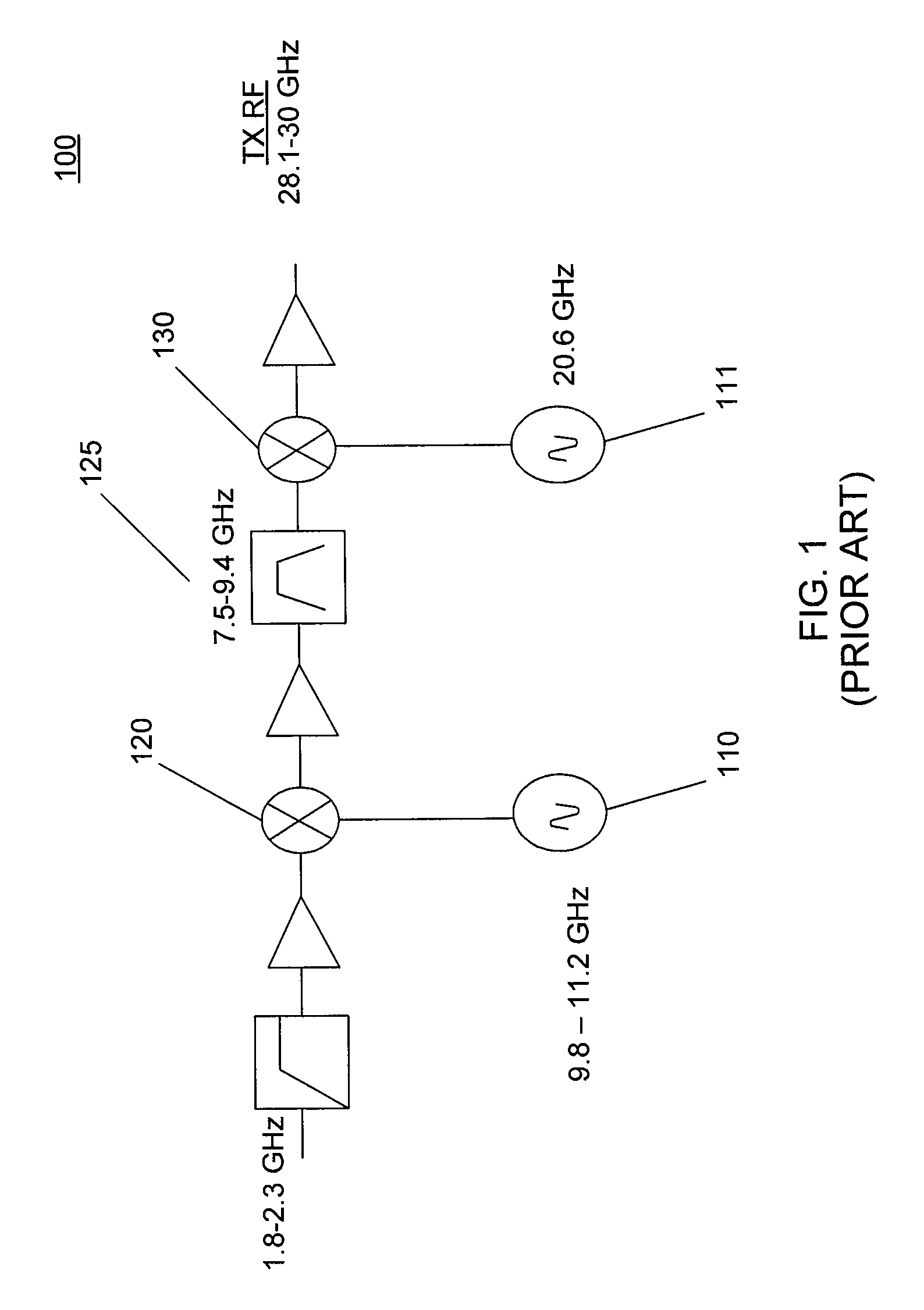
In this embodiment, spurious signals can be difficult to filter because IF related spurious signals are typically a small percentage away from generally desired RF passbands.
Thus, resulting in unnecessarily high material costs.
Furthermore, the final upconversion uses a local oscillator at a high frequency that is more difficult to design with adequate phase noise than the first LO.
Wider filter passbands employed by such prior art may be difficult if not impossible to design because, in some instances, undesired higher order spurious mixer outputs related to multiples of LO and IF input frequencies may be too close to the pass-band to adequately filter or may even be inside the filter pass-band thus prohibiting a single filter approach.
In any event, it may be difficult to design a cost effective device comprising multiple local oscillators in tunable transmitters with a dual conversion architecture.
In some instances, use of such prior art designs may also necessitate use of a switchable bank of filters, which increases overall design cost.
Use of prior art architecture also renders it difficult if not practically impossible to use highly integrated GaAs, silicon-germanium (SiGe) or other semiconductor processes in tunable transmitters and obtain sufficient spurious rejection, due to process variations that give rise to additional design limitations.

Method used


Image

  • Dual conversion transmitter with single local oscillator
  • Dual conversion transmitter with single local oscillator
  • Dual conversion transmitter with single local oscillator

Examples


Embodiment Construction

[0029]While exemplary embodiments are described herein in sufficient detail to enable those skilled in the art to practice the invention, it should be understood that other embodiments may be realized and that logical electrical and mechanical changes may be made without departing from the spirit and scope of the invention. Thus, the following detailed description is presented for purposes of illustration only.

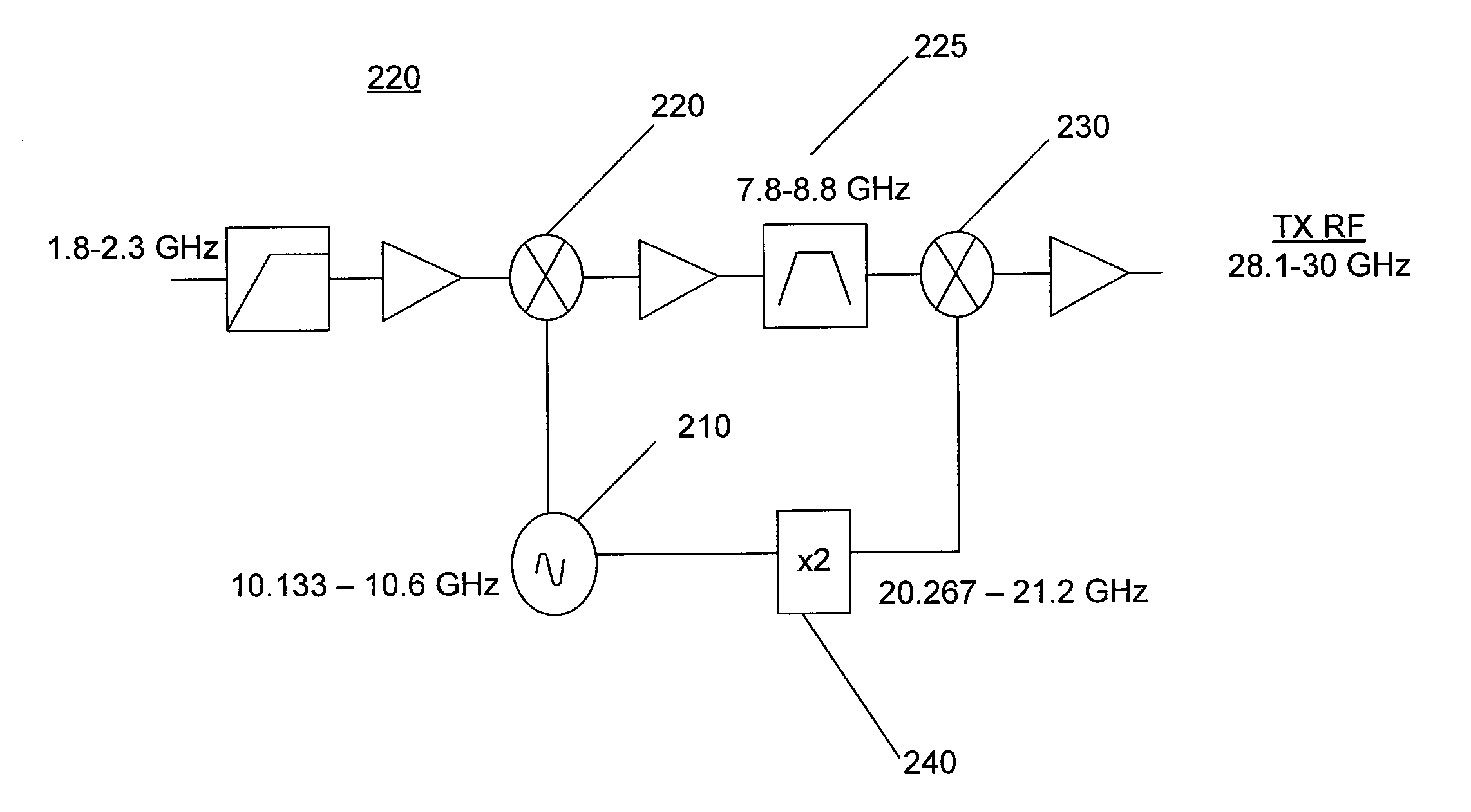
[0030]In accordance with an exemplary embodiment of the present invention, a tunable transmitter with dual conversion architecture comprises a single tunable oscillator. The single tunable oscillator provides a local oscillator (“LO”) signal to a first mixer and provides a scaled version of the LO signal to a second mixer. The first mixer upconverts an IF signal which is filtered, and the filtered signal is then upconverted in the second mixer. The output of the second mixer is an RF signal. The RF signal may be transmitted via an antenna, for example. Although described herei...


PUM


Abstract

The present disclosure relates to systems, devices and methods related to transmitters, and / or transceivers having a single, tunable oscillator in a dual conversion architecture. In various exemplary embodiments, this transmitter may include: a first mixer configured to receive a first oscillator signal from the single oscillator; a filter configured to band pass filter the converted signal and output a filtered signal; and a second mixer in communication with the filter, configured to receive the filtered signal. This dual conversion transmitter may be configured to receive a communication signal from an input to the transmitter and to output a converted signal based on the first oscillator signal and the communication signal. The second mixer may be configured to receive a scaled version of the first oscillator signal and to output a desired frequency output signal based on the scaled version of the first oscillator signal and the filtered signal.

Description

CROSS REFERENCE TO RELATED APPLICATIONS[0001]This application claims the benefit of, and priority to, provisional patent application having Ser. No. 61 / 112,538 filed Nov. 7, 2008 entitled “DUAL CONVERSION TRANSMITTER WITH SINGLE LOCAL OSCILLATOR”.FIELD OF INVENTION[0002]The present invention relates to transmitters, and / or transceivers. More particularly, the invention relates to systems, devices and methods related to transmitters, and / or transceivers having a single, tunable oscillator in a dual conversion architecture.BACKGROUND OF THE INVENTION[0003]Various existing transmitters, and / or transceivers (herein after transmitter(s)) may employ a dual conversion architecture for up or down conversion of radio frequency (“RF”) signals. Such a transmitter is generally configured in the prior art to use two, separate local oscillators. More particularly, when the transmitter is a tunable transmitter, the dual conversion architecture comprises two or more separate local oscillators.[0004...

Claims


Application Information

Patent Timeline
Patent Type & Authority Patents(United States)
IPC IPC(8): H04B1/04H01Q11/12
CPCH03D7/163
Inventor LORG, SHAWN M.BUER, KENNETH V.
Owner VIASAT INC
Learn More