Legged robot and its control method

a robot and control method technology, applied in the field of legged robots, can solve the problems of difficult to generate trajectory data, no configuration information that enables real-time generation of walking and running trajectories, etc., and achieve the effect of flexibly generating various motion patterns, flexibly generating trajectory data, and flexibly generating desired trajectory data

Inactive Publication Date: 2013-02-26
TOYOTA JIDOSHA KK
View PDF32 Cites 38 Cited by
  • Summary
  • Abstract
  • Description
  • Claims
  • Application Information

AI Technical Summary

Benefits of technology

[0011]Calculating the trajectory (the center of gravity position and the leg tip position and posture) in stepping motion in this way enables easy creation of a model of stable trajectory data, and superimposing a travel velocity onto the calculated stepping trajectory to deform it enables generation of a desired one-step trajectory according to the travel velocity. It is thereby possible to flexibly generate various motion patterns.
[0024]According to the embodiments of the present invention described above, it is possible to provide a legged robot and its control method capable of generating various motion patterns flexibly.

Problems solved by technology

However, the related art described in Japanese Unexamined Patent Application Publication No. 2006-212736 or the like discloses nothing about the way of designating velocity boundary condition in one-step interval for various walking and running patterns.
Further, the related art discloses nothing about the configuration that enables generation of walking and running trajectories in real time with the use of a technique of determining the velocity boundary condition of a one-step trajectory.
As described in the foregoing, it has been difficult to generate trajectory data by setting adequate velocity boundary condition in advance for various walking and running patterns, and the related art can only realize the previously regulated limited pattern.

Method used


Image

  • Legged robot and its control method
  • Legged robot and its control method
  • Legged robot and its control method

Examples


first embodiment

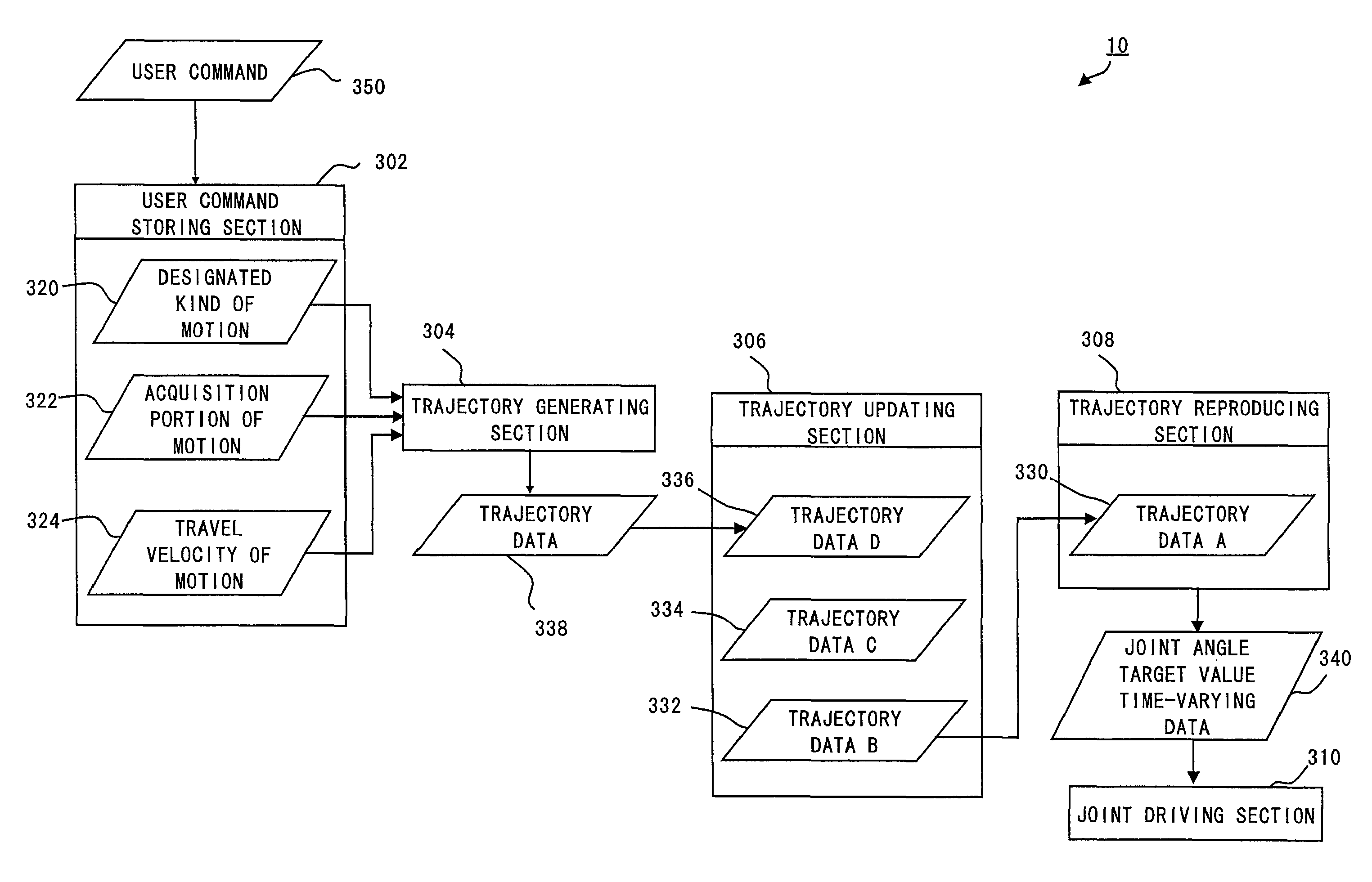
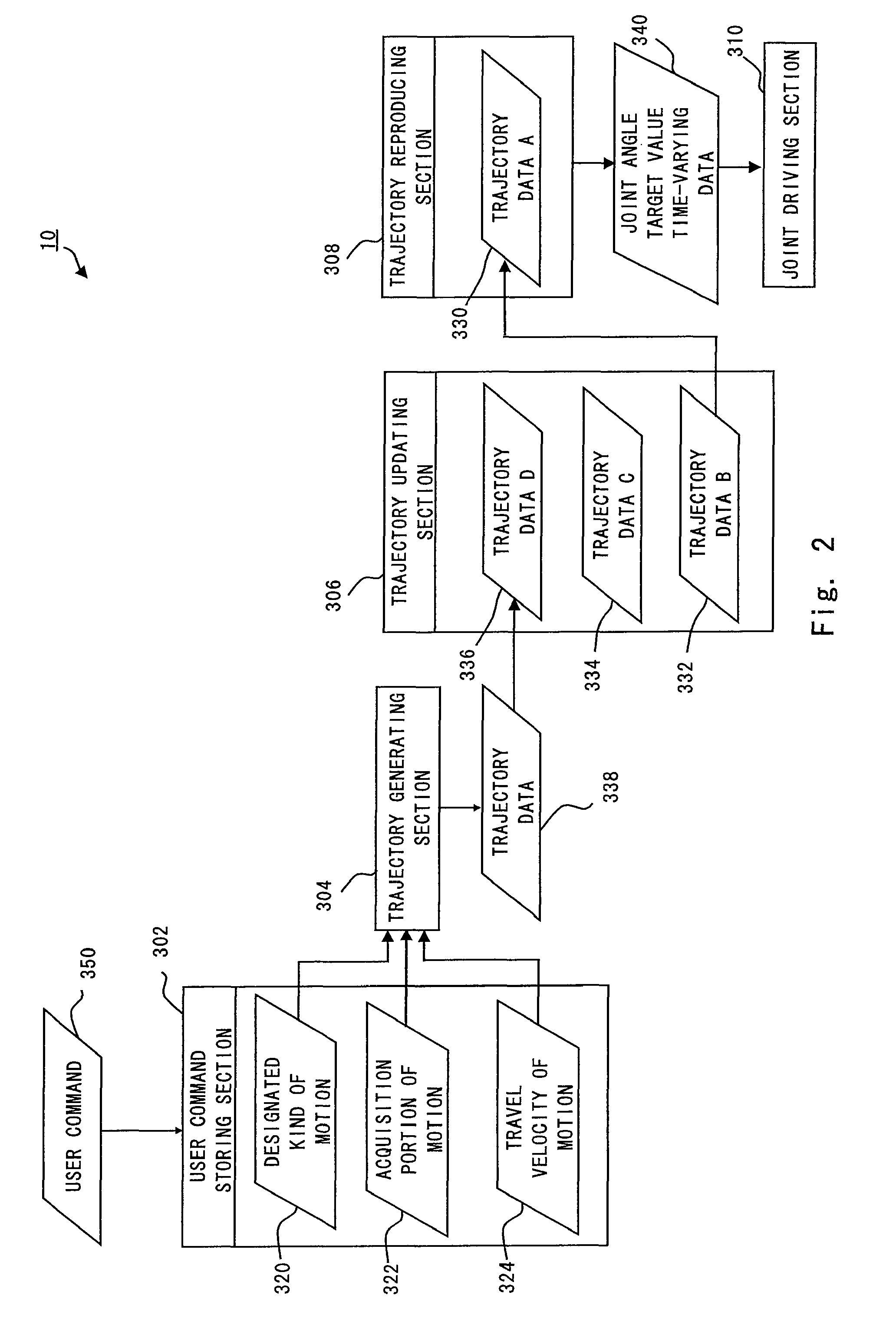
[0034]A legged robot according to a first embodiment of the present invention first calculates a trajectory of the center of gravity in designated stepping motion. Next, it acquires a designated portion of the calculated stepping trajectory. Then, it superimposes a travel velocity onto the acquired trajectory portion to deform it. Based on the deformed trajectory of the center of gravity, the legged robot performs motion by changing the joint angle.

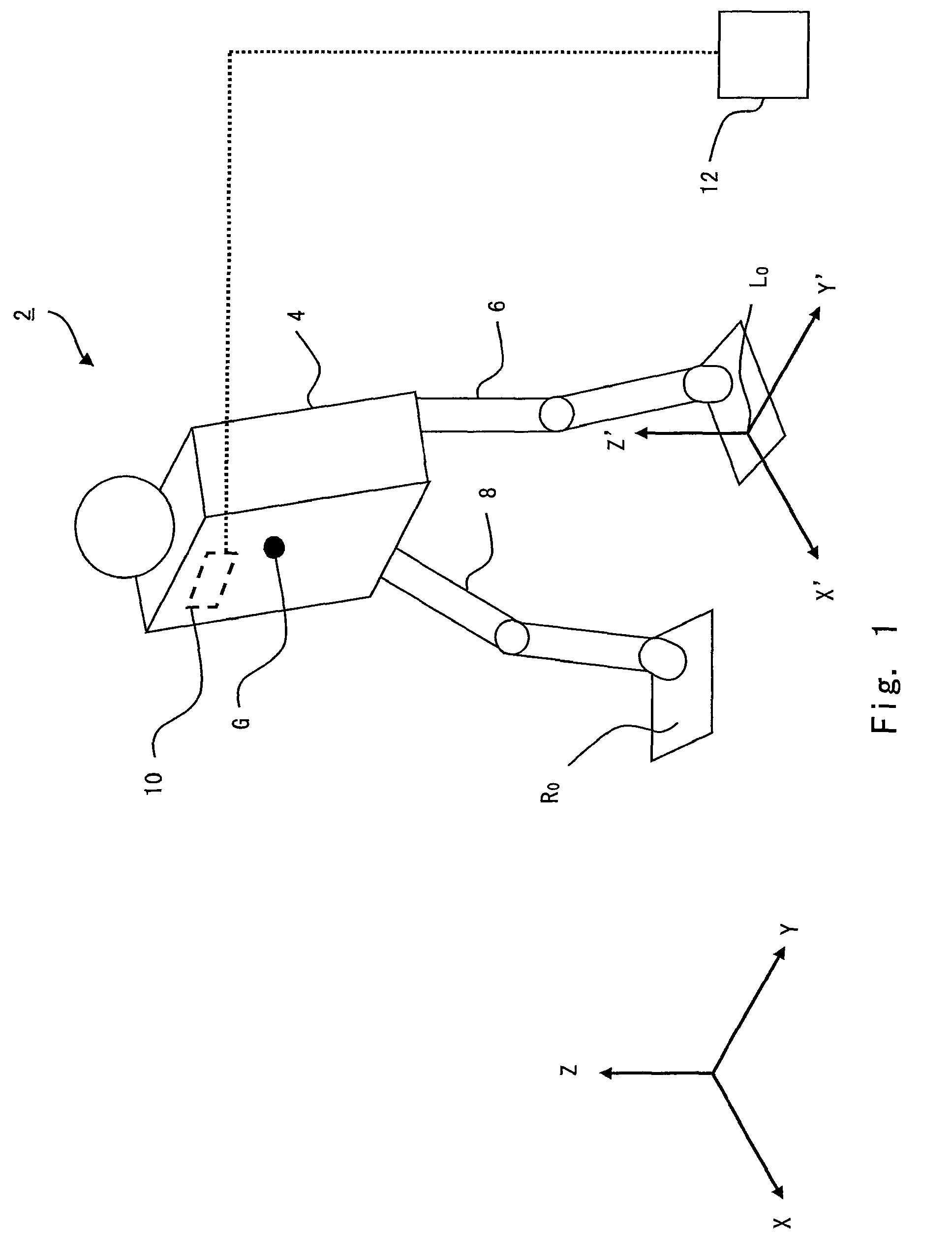
[0035]A trajectory calculation method of a robot according to the first embodiment of the present invention is described hereinafter with reference to the drawings. FIG. 1 is a view showing the outline of the legged robot according to the first embodiment. A robot 2 includes a trunk 4, a left leg link 6, a right leg link 8, a control unit 10 and a controller 12. One end of the left leg link 6 is rotatably coupled to the trunk 4 through a hip joint. The left leg link 6 includes a knee joint and an ankle joint and further includes a foot at...


PUM


Abstract

There is provided a legged robot that performs motion by changing a joint angle, which includes a trajectory generating section to calculate a center-of-gravity trajectory in designated stepping motion from the stepping motion including at least one of walking motion, running motion and stopping motion, and generate a center-of-gravity trajectory by superimposing a designated travel velocity onto a travel velocity of a center of gravity in the calculated center-of-gravity trajectory in stepping motion, and a trajectory updating section to store the generated center-of-gravity trajectory and update all the stored center-of-gravity trajectories so as to be continuous, and a trajectory reproducing section to calculate time-varying data of a target value of the joint angle based on the updated center-of-gravity trajectory, and a joint driving section to rotate a joint of the legged robot based on the calculated time-varying data of a target value of the joint angle.

Description

BACKGROUND OF THE INVENTION[0001]1. Field of the Invention[0002]The present invention relates to a legged robot that performs motion by changing a joint angle and its control method.[0003]2. Description of Related Art[0004]Various techniques have been proposed for generating a walking trajectory of a legged walking robot. As one technique of generating a walking trajectory of a legged walking robot, a technique of generating walking motion of a robot by designating the vertical movement of the center of gravity to thereby calculate an optimum landing position with no falling down in real time is known (e.g. Japanese Unexamined Patent Application Publication Nos. 2006-212736 and 2004-167676). In this description, the term “trajectory” refers to data that describes a change in position over time.[0005]The technique of the related art as described in Japanese Unexamined Patent Application Publication No. 2006-212736, for example, designates the landing positions of the foot for a plura...

Claims


Application Information

Patent Timeline
Patent Type & Authority Patents(United States)
IPC IPC(8): G06F19/00B25J5/00
CPCB62D57/032
Inventor HONDA, DAISAKUSUGA, KEISUKETAJIMA, RYOSUKE
Owner TOYOTA JIDOSHA KK
Why Eureka
Try Eureka