Injector flow measurement for fuel cell applications

a fuel cell and injector technology, applied in fluid tightness measurement, instruments, electrochemical generators, etc., can solve the problem of relatively high cost of meas

Active Publication Date: 2013-03-05
GM GLOBAL TECH OPERATIONS LLC
View PDF24 Cites 30 Cited by
  • Summary
  • Abstract
  • Description
  • Claims
  • Application Information

AI Technical Summary

Problems solved by technology

MEAs are relatively expensive to manufacture and require certain conditions for effective operation.

Method used


Image

  • Injector flow measurement for fuel cell applications
  • Injector flow measurement for fuel cell applications
  • Injector flow measurement for fuel cell applications

Examples


Embodiment Construction

[0018]The following discussion of the embodiments of the invention directed to a method for determining the amount of fuel flow to a fuel cell stack using anode sub-system pressures is merely exemplary in nature, and is in no way intended to limit the invention or its applications or uses. For example, the present invention has particular application for a fuel cell system on a vehicle. However, as will be appreciated by those skilled in the art, the method of the invention may have applications for other types of fuel cell systems.

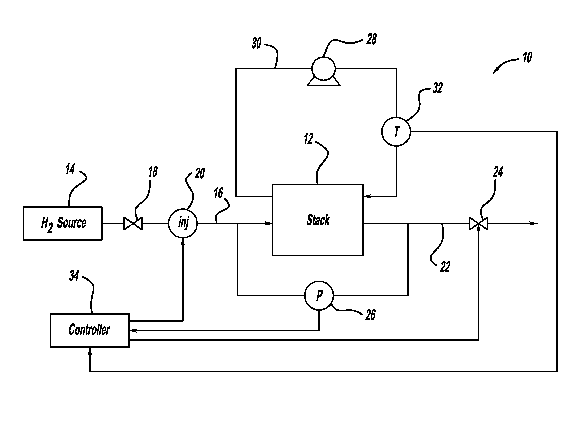
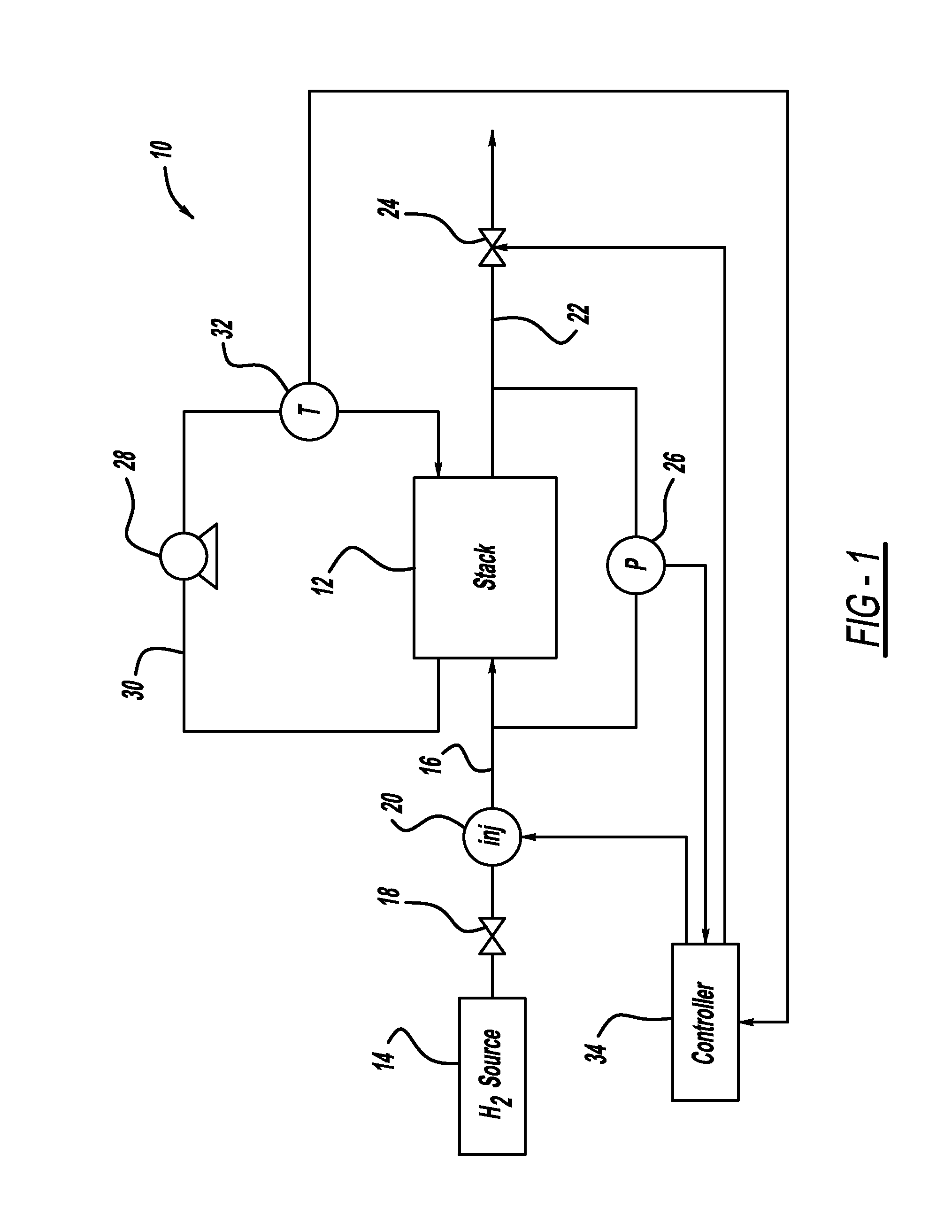
[0019]FIG. 1 is a schematic block diagram of a fuel cell system 10 including a fuel cell stack 12. Hydrogen gas from a high pressure hydrogen gas source 14, such as a tank, is provided to the anode side of the fuel cell stack 12 on anode input line 16. The hydrogen gas from the source 14 is regulated by a pressure regulator 18 and injected into the stack 12 by an injector 20. The injector 20 is intended to represent a single injector or a bank of injector...


PUM


Abstract

A method for determining the amount of fuel flow from a high pressure gas tank to the anode side of a fuel cell stack through pulsed injector. The anode sub-system pressure is measured just before the injector pulse and just after injector pulse and a difference between the pressures is determined. The difference between the pressures, the volume of the anode sub-system, the ideal gas constant, the anode sub-system temperature, the fuel consumed from the reaction in the fuel cell stack during the injection event and the fuel cross-over through membranes in the fuel cells of the fuel cell stack are used to determine the amount of hydrogen gas injected by the injector.

Description

BACKGROUND OF THE INVENTION[0001]1. Field of the Invention[0002]This invention relates generally to a method for determining a metered flow of hydrogen fuel to a fuel cell stack and, more particularly, to a method for determining a metered flow of hydrogen fuel through a pulsed injector to a fuel cell stack that uses anode sub-system pressure before the pulsed injection and after the pulsed injection.[0003]2. Discussion of the Related Art[0004]Hydrogen is a very attractive fuel because it is clean and can be used to efficiently produce electricity in a fuel cell. A hydrogen fuel cell is an electro-chemical device that includes an anode and a cathode with an electrolyte therebetween. The anode receives hydrogen gas and the cathode receives oxygen or air. The hydrogen gas is dissociated at the anode catalyst to generate free protons and electrons. The protons pass through the electrolyte to the cathode. The protons react with the oxygen and the electrons at the cathode catalyst to gen...

Claims


Application Information

Patent Timeline
Patent Type & Authority Patents(United States)
IPC IPC(8): G01M3/26
CPCG01F1/34G01F1/363G01F1/40G01F1/72G01M3/26H01M8/04388H01M8/04753H01M2008/1095Y02E60/50
Inventor FALTA, STEVEN R.GOEBEL, STEVEN G.DI FIORE, DANIEL C.SENNER, RALF
Owner GM GLOBAL TECH OPERATIONS LLC
Why Eureka
Try Eureka