Top feeder for a sewing machine

a top feeder and sewing machine technology, applied in the field of sewing machines, can solve the problems of affecting the work of the user of the sewing machine, the limitation of the function of the top feeder, and the way the user is disturbed, so as to avoid the marks on the pieces, prevent the shearing of the pieces, and improve the feed of cloth

Active Publication Date: 2013-03-05
SINGER SOURCING LTD LLC
View PDF9 Cites 12 Cited by
  • Summary
  • Abstract
  • Description
  • Claims
  • Application Information

AI Technical Summary

Benefits of technology

[0008]One of the advantages with the arrangement according to the invention is that it will be possible to set a desired pressure of the top feeder against the cloth or the multiple layers of cloth. Many different types of cloth exist differing from each other with respect to density, thickness, friction, etc., whereby a controlled pressure exerted by the top feeder as a result will improve the feed of the cloth during sewing. As an example, if two low friction pieces of cloth are sewn together, a high pressure is desirable to prevent shearing of the pieces of cloth, whereas during sewing on very thin pieces of cloth a lower pressure will be favourable in order to avoid marks on the pieces of cloth.
[0009]A further advantage is that it will be possible to determine the pressure the top feeder will exert on the cloth irrespective of variations of the thickness of the cloth or the thickness of multiple cloth layers to be sewn together.

Problems solved by technology

A solution of this kind has limitations of the function of the top feeder.
For example, when the top feeder is not in use and being swung away, it can be in the way and disturb the work for a user of the sewing machine.

Method used


Image

  • Top feeder for a sewing machine
  • Top feeder for a sewing machine
  • Top feeder for a sewing machine

Examples


Embodiment Construction

[0014]Below, the invention will be explained in greater detail by description of at least one enabling embodiment with reference to the accompanying drawings.

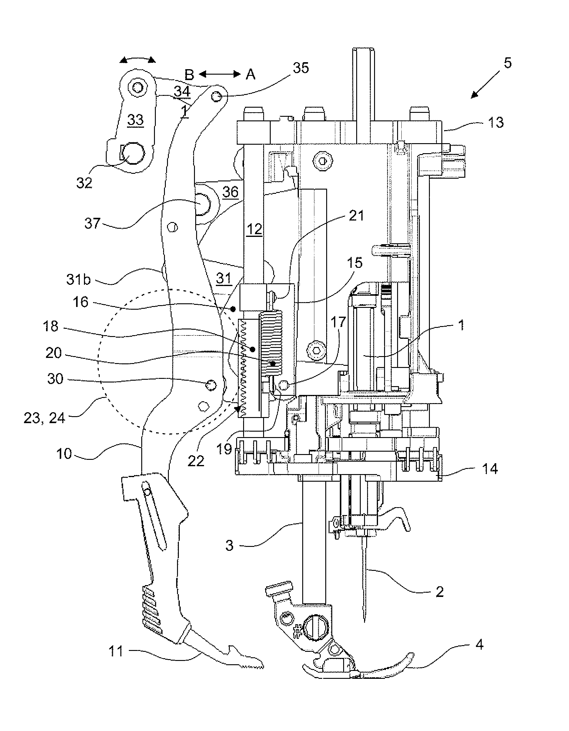
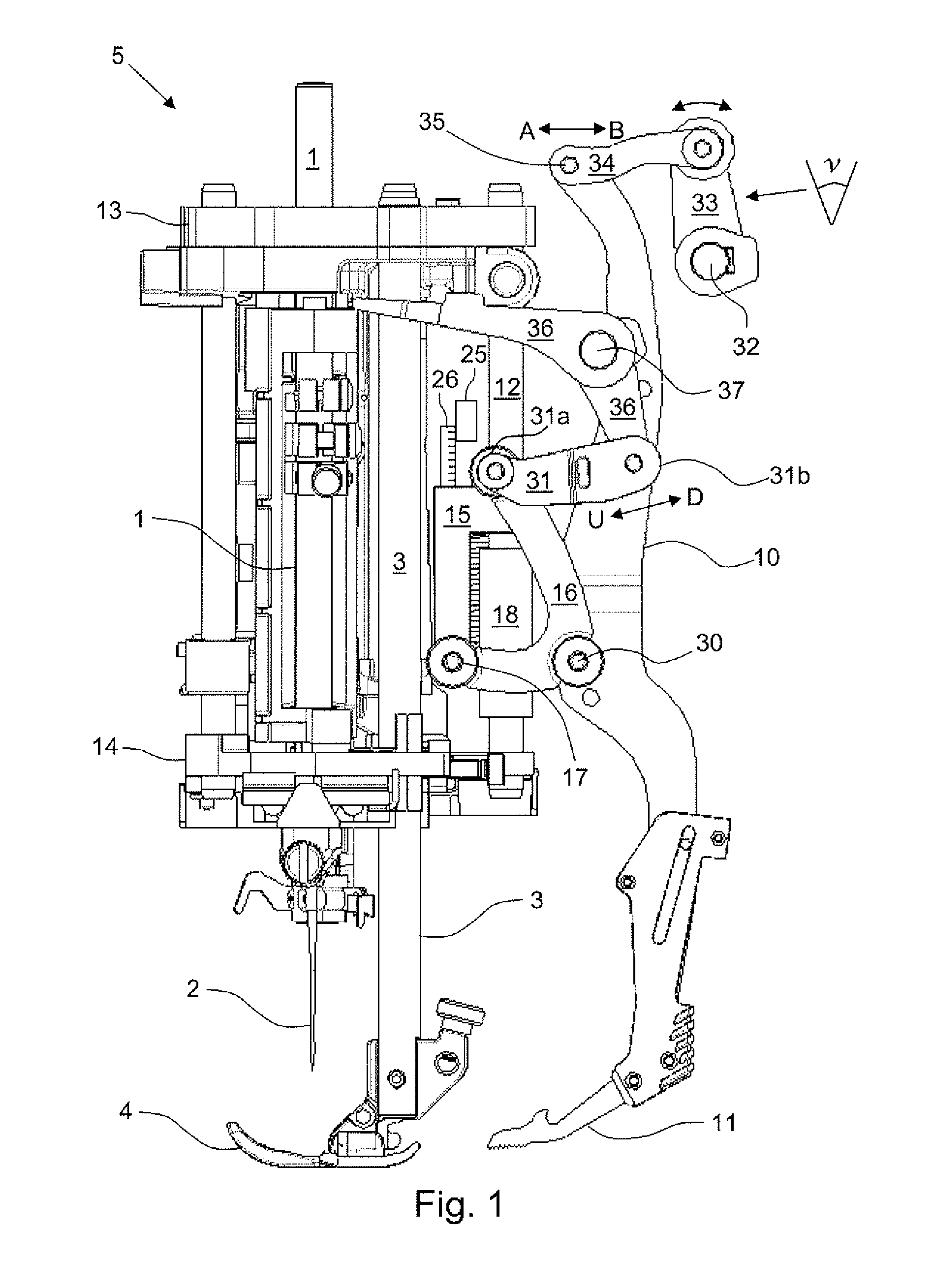
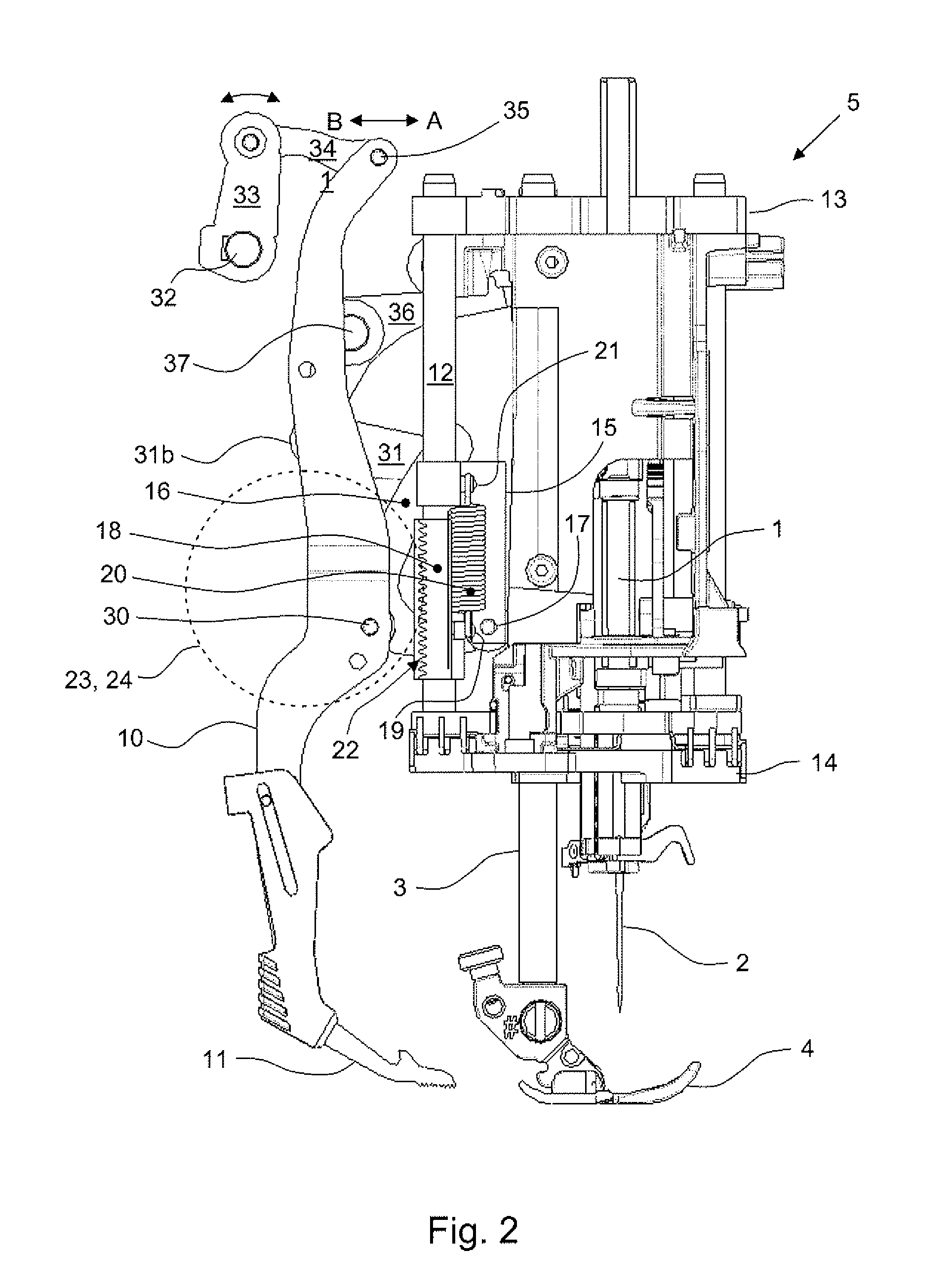
[0015]The arrangement shown in the drawings represents a portion of a domestic sewing machine, herein called a sewing head. Said arrangement comprises a vertically movable needle bar 1 provided with a needle 2 and a likewise vertically movable presser bar 3 provided with a presser foot 4.

[0016]According to one embodiment of the present invention, presented in the following, the arrangement is further provided with a top feeder arm 10 having a top feeder 11 at its lower end. The purpose with the top feeder 11 is to feed a cloth inserted in the sewing machine by acting from the upper side of the cloth. Said feed is performed in a cyclic movement mechanically controlled by the drive shafts of the sewing machine according to prior art. The feed using said top feeder is thus synchronized with the feed of the cloth, during sewing, fr...


PUM


Abstract

A top feeder arrangement for a sewing machine provided with a processor for controlling stitches sewn on a cloth, wherein the sewing machine has a sewing machine head which comprises a needle mechanism with a needle bar (1) provided with a needle (2), a presser bar (3) provided with a presser foot (4) and a top feeder arm (10) provided at its lower end with a top feeder (11) acting from an upper surface of a cloth for feeding the cloth in the sewing direction and wherein the sewing machine is provided with a mechanism (12, 15, 17, 18) providing a controllable pressure of the top feeder (11) against the cloth.

Description

TECHNICAL FIELD[0001]The present invention relates in general to sewing machines and in particular to a top feeder acting from the upper side of a piece of cloth being sewn for feeding said piece of cloth.BACKGROUND OF THE INVENTION[0002]Top feeders are known in prior art, for example through document U.S. Pat. No. 4,611,548. In said document it is described a top feeder providing a kinematically lifting drive for a top transport device, herein called a top feeder, as already indicated above, wherein the top feeder and a presser bar of the sewing machine are interconnected to each other. By this, according to the statements of the description, a space-saving arrangement of a top feeder rocker is achieved, of a seating for the top feeder and of the top feeder lifting drive. Through this arrangement it is achieved that a spring pressure acting on the top feeder extends essentially in the region of the axis of the presser bar such that lateral forces thereby are avoided.[0003]In the to...

Claims


Application Information

Patent Timeline
Patent Type & Authority Patents(United States)
IPC IPC(8): D05B27/06
CPCD05B27/04
Inventor BARDH, JONASHAKANSSON, ESKIL
Owner SINGER SOURCING LTD LLC
Why Eureka
Try Eureka