
Electrical connectors having opposing electrical contacts

Active Publication Date: 2013-03-05
TE CONNECTIVITY CORP
View PDF7 Cites 76 Cited by
  • Summary
  • Abstract
  • Description
  • Claims
  • Application Information

AI Technical Summary

Benefits of technology

The solution enables independent electrical engagement of conductive components, accommodating misalignment while ensuring each contact can operate at different voltages and carry different currents, enhancing the flexibility and functionality of electrical connectors.

Problems solved by technology

As such, the mating contacts are electrically common and unable to carry different currents and operate at different voltages.

Method used


Image

  • Electrical connectors having opposing electrical contacts
  • Electrical connectors having opposing electrical contacts
  • Electrical connectors having opposing electrical contacts

Examples


Embodiment Construction

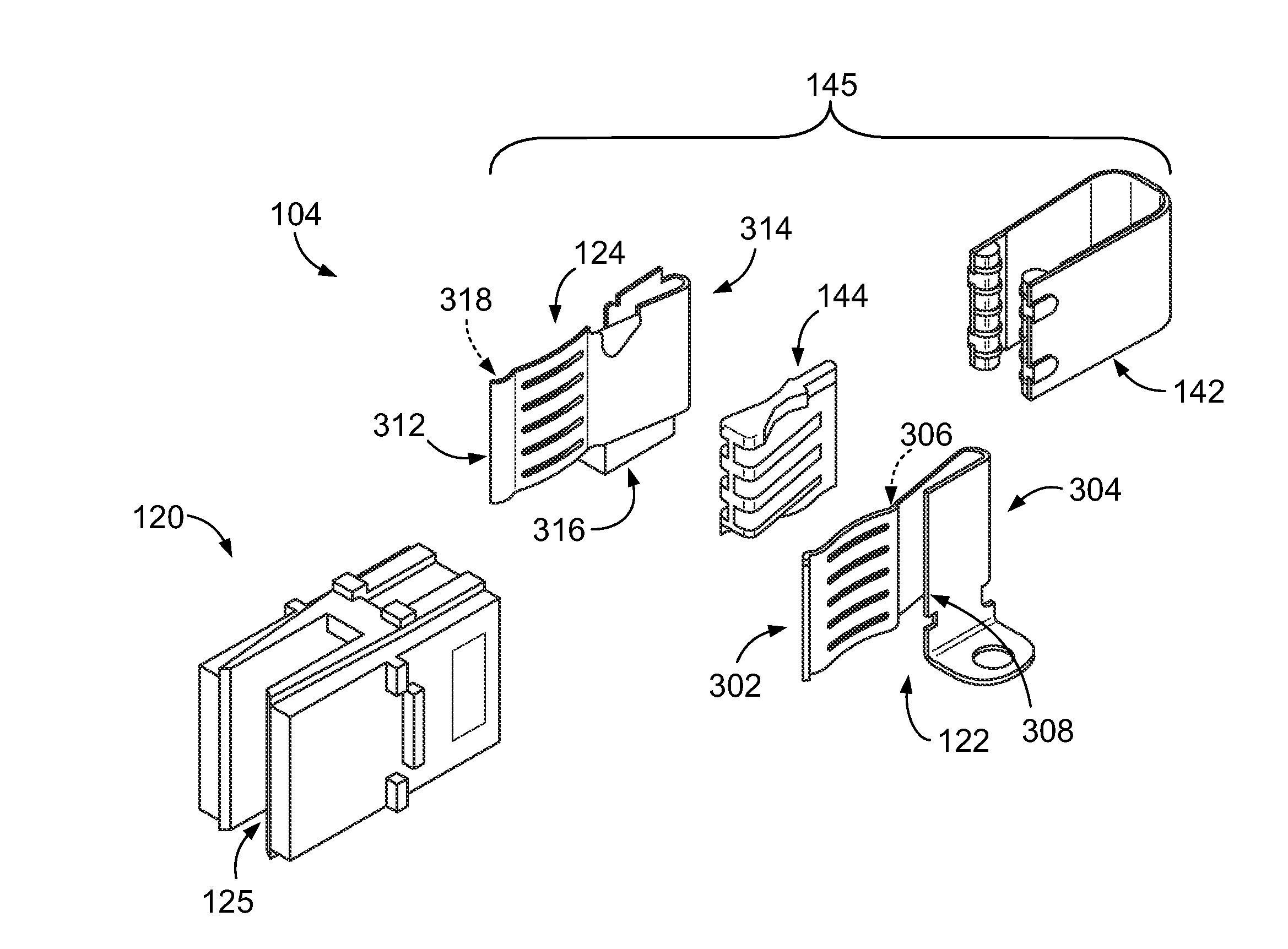
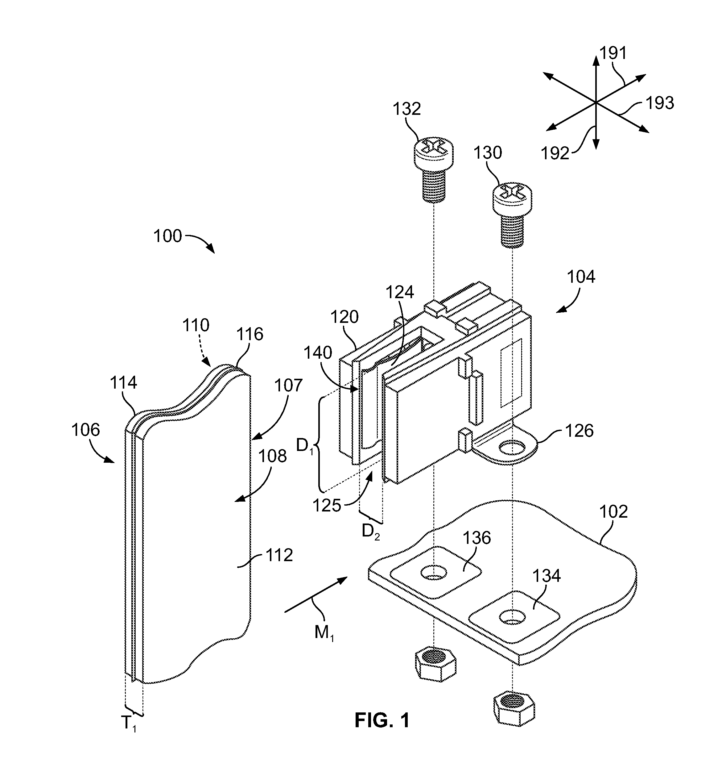
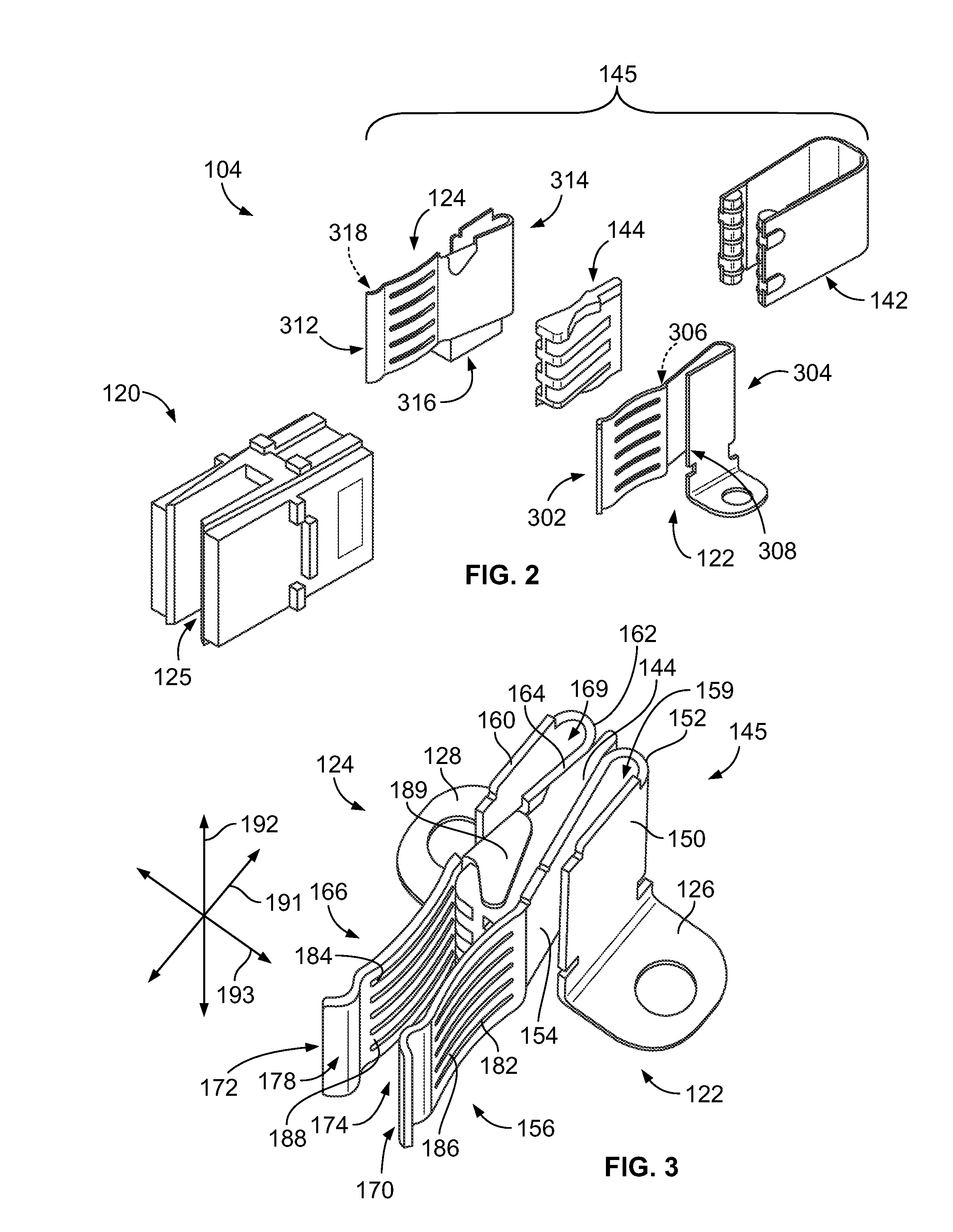
[0014]FIG. 1 is an exploded view of an electrical system 100 formed in accordance with one embodiment. As shown, the electrical system 100 includes an electrical element 102 (e.g., a circuit board), an electrical connector 104 that is configured to be mounted to the electrical element 102, and a conductive component 106 that is configured to communicatively engage the electrical connector 104. The conductive component 106 includes a leading edge 107 that is configured to be received by the electrical connector 104. In an exemplary embodiment, the conductive component 106 is a busbar and the electrical connector 104 includes electrical contacts 122 (shown in FIG. 2) and 124 that are configured to transmit electrical power therethrough. However, in other embodiments, the conductive component 106 may be, for example, a card connector and the electrical connector 104 may have electrical contacts configured to transmit data signals therethrough. The conductive component 106 could also be...


PUM


Abstract

Electrical connector that includes a pair of electrical contacts. Each of the electrical contacts has a mounting portion and a flexible mating portion that is configured to electrically engage a conductive component. The mating portions of the electrical contacts are separated by a component-receiving space and oppose each other across the component-receiving space. The electrical connector also includes a spring clip that is configured to mechanically engage the mating portions and is movable with respect to the mounting portions. The spring clip has a pair of opposing clip arms and a bridge member that joins the clip arms. The clip arms are separated by a gap with the mating portions positioned therebetween. The clip arms are biased against the corresponding mating portions. The spring clip has a dielectric member that is positioned to electrically isolate at least one of the electrical contacts.

Description

BACKGROUND OF THE INVENTION[0001]The subject matter described and / or illustrated herein relates generally to electrical connectors that have opposing electrical contacts configured to engage opposite sides of a conductive component.[0002]In some electrical systems, power is delivered to a circuit board or other electrical component through a busbar and a busbar connector. A busbar typically comprises a planar strip of conductive material (e.g., copper) having opposite sides which are engaged by the busbar connector. Existing busbar connectors include a housing that holds two mating contacts that oppose each other with a space therebetween. When the busbar is inserted into the space, each of the mating contacts electrically engages a corresponding side of the busbar. In some connectors, the mating contacts are configured to adjust if the busbar is inserted into the space in a misaligned manner. For instance, when the busbar is misaligned, the busbar may press against a first mating c...

Claims


Application Information

Patent Timeline
Patent Type & Authority Patents(United States)
IPC IPC(8): H01R4/48
CPCH01R13/18H01R13/26H01R13/113
Inventor COSTELLO, BRIAN PATRICKORRIS, DAVID PATRICK
Owner TE CONNECTIVITY CORP
Learn More