
Automated memorial system

a memorial system and automatic technology, applied in the direction of electric discharge lamps, discharge tube/lamp details, incandescent screens, etc., can solve the problems of loss of illumination, failure to illuminate the appropriate individual, and the bulb that should be lit has reached the end of its life cycl

Active Publication Date: 2013-03-05
ZAGHA MAURICE
View PDF9 Cites 14 Cited by
  • Summary
  • Abstract
  • Description
  • Claims
  • Application Information

AI Technical Summary

Benefits of technology

The patent describes an automated memorial system that uses light sources to create various runs of lighting opportunities. These light sources are commonly strung together to create different sizes of the system. The technical effect of this invention is a more flexible and customizable automated memorial system that provides unparalleled control and flexibility for users.

Problems solved by technology

It will be appreciated that in large congregations, large numbers of individuals can be displayed on one or more such memorial boards, and the task of managing the appropriate illumination of light bulbs for the individuals can be time consuming and error prone where such errors can result in the failure to illuminate the appropriate individual at the appropriate time.
Compounding the problem with maintaining the appropriate illumination of lights is the life cycle of the traditional incandescent bulbs used in a conventional memorial board that can result in a loss of illumination when the end of the life cycle is reached.
Unless, a bulb fails to illuminate at the time it is manually activated, there is no easy way to detect when a bulb that should be lit has reached the end of its life cycle without periodically manually checking each bulb in the one or more memorial boards.
As the light bulbs are each subject to individual and manual activation, there is no easy way to quickly check whether an individual bulb has gone out and requires replacement.

Method used


Image

  • Automated memorial system
  • Automated memorial system
  • Automated memorial system

Examples


Embodiment Construction

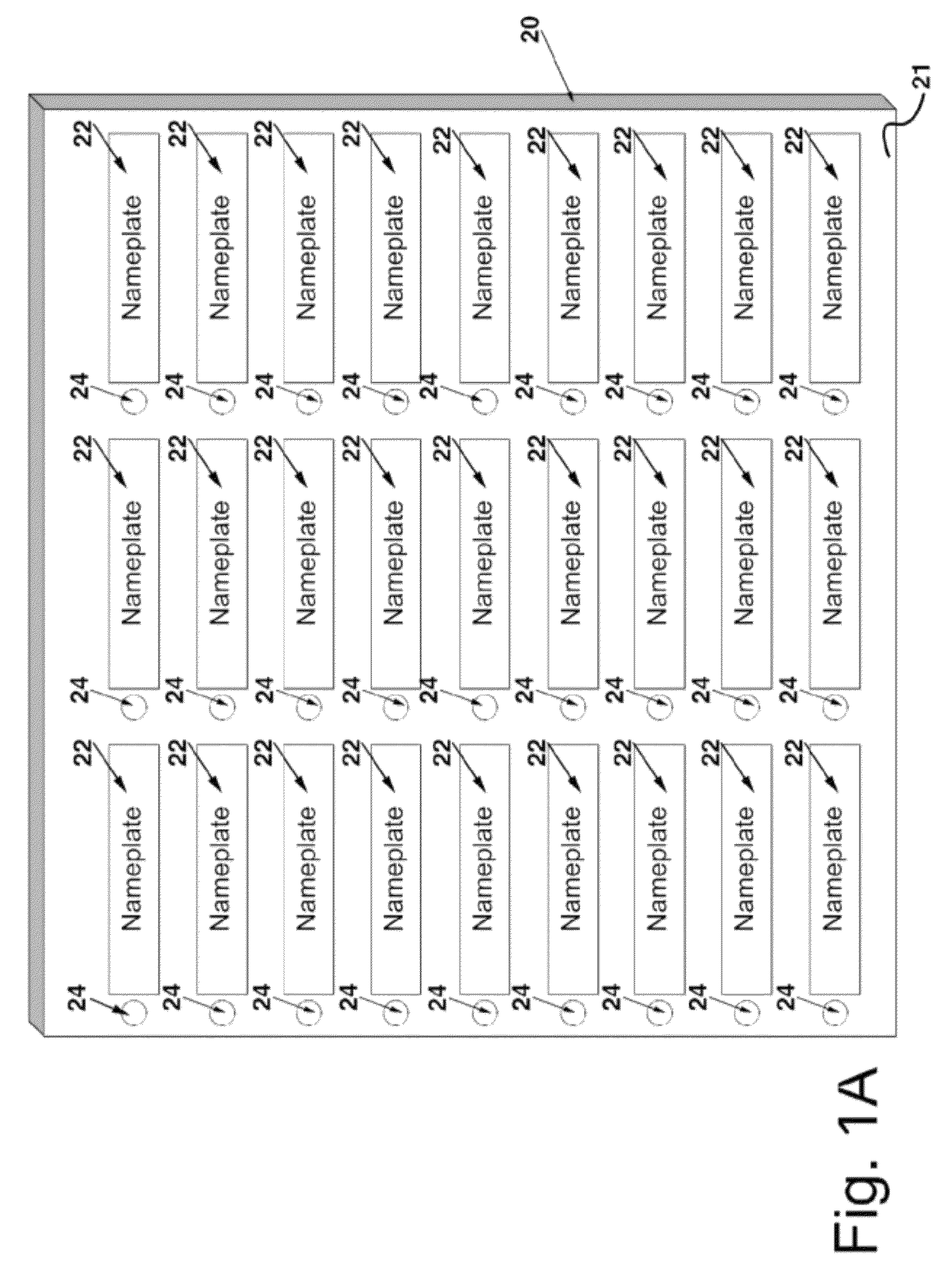
[0029]With reference to the drawings for purposes of illustration, a memorial device 20 (FIG. 1A) having a housing 21 includes a plurality of nameplates 22 and associated light fixtures 24 configured conventionally in rows and columns on a front surface of the housing. Advantageously, each light fixture includes at least one low voltage light source such as a light emitting diode (LED).

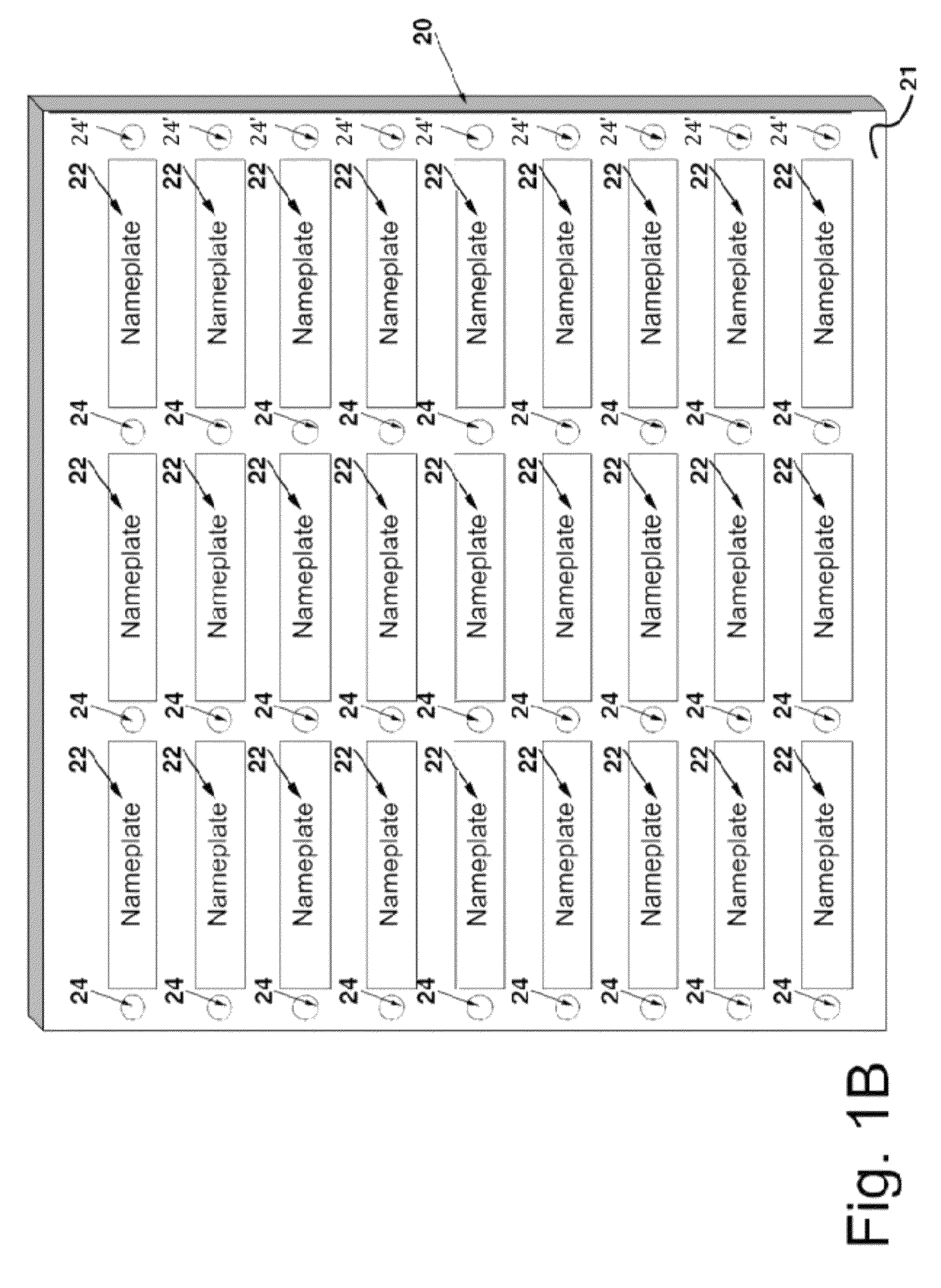
[0030]Similarly, a memorial device 20 (FIG. 1B) having a housing 21 includes a plurality of nameplates 22 and associated light fixtures 24 configured conventionally in rows and columns on a front surface of the housing. Additionally, one extra column of light fixtures 24′ is provided to permit illumination either or both sides of any nameplate. As in FIG. 1A, advantageously, each light fixture includes at least one low voltage light source such as a light emitting diode (LED).

[0031]While shown and described in a conventional ornamentation, the memorial device 20 according to the present invention shou...


PUM


Abstract

A memorial display system is described including at least one memorial device having a plurality light fixtures with each light fixture having at least one light source. Each of the light sources are in electrical communication with a controller circuit that automatically activates and deactivates the at least one light source of each light fixture according to at least one anniversary date and for a duration period stored in the memory. In one embodiment, each light source is part of a light bar with up to 5 lights. The light bars are commonly strung together to create various runs of lighting opportunities allowing for different overall sizes of the automated memorial system.

Description

CROSS-REFERENCE TO RELATED APPLICATION(S)[0001]This application claims the benefit of co-pending U.S. provisional application Ser. No. 61 / 151,146 filed on Feb. 9, 2009, which is incorporated herein by reference.BACKGROUND OF THE INVENTION[0002]1. Field of the Invention[0003]This invention relates generally to anniversary reminder systems, and, more particularly, to a centralized system for automatically tracking multiple anniversaries.[0004]2. Description of the Related Art[0005]Throughout the world and in connection with many secular as well as religious traditions, a lighted candle is often associated with an anniversary or a time of remembrance, reflection or prayer. Often, the passing of an anniversary or time of remembrance results in the lighting of a candle. In some Christian faiths, votive candles may be lit to represent a time of remembrance or prayer. In Judaism, the anniversary of the death of a parent or close relative, commonly observed by burning a candle for an approp...

Claims


Application Information

Patent Timeline
Patent Type & Authority Patents(United States)
IPC IPC(8): H05B37/02
CPCH05B37/0281Y02B20/42H05B47/16H05B47/175Y02B20/40
Inventor ZAGHA, MAURICE
Owner ZAGHA MAURICE
Learn More