Unidirectional fixation device

a fixation device and unidirectional technology, applied in the field of spine fixation devices, can solve the problems of increasing the attachment alternatives of the fasteners, subsidence may tend to shift more spinal load to the plate than the spinal load, and load shifting can occur

Active Publication Date: 2006-09-28
SYNTHES USA
View PDF10 Cites 34 Cited by
  • Summary
  • Abstract
  • Description
  • Claims
  • Application Information

AI Technical Summary

Benefits of technology

[0018] A fixation system kit is also described comprising a plurality of carriage elements capable of receiving one or more bone fasteners, each having a first channel with a least one securing element disposed therein; at least one plate having arms insertable in a channel; wherein each arm has a first engaging portion, the first engaging portion having a series of ridges configured to engage a securing element; and wherein at least two of the carriage elements are of a substantially different size. The kit may further comprise at least one bone fastener.

Problems solved by technology

However, polyaxial movement of fasteners through set plate hole locations only increases attachment alternatives of the fasteners themselves.
Where a rigid fixation plate is used to connect the vertebrae, this subsidence may tend to shift more of the spinal load to the plate than is desirable.
Such load shifting can also occur due to inaccuracies in installing the plate to the vertebrae.
In extreme circumstances, this load shifting can result in non-fusion of the spacer to the vertebra, since firm compression between the spacer and the vertebrae is one factor contributing to successful fusion.
However, fasteners used with both rigid and translational plates have a tendency to back-out of their installed positions under the influence of force and movements of the spine.
The back-out of the fasteners is undesirable, as the fixation assembly may shift post-operatively to an undesired location, or loosen to an undesirable level.

Method used


Image

  • Unidirectional fixation device
  • Unidirectional fixation device
  • Unidirectional fixation device

Examples


Embodiment Construction

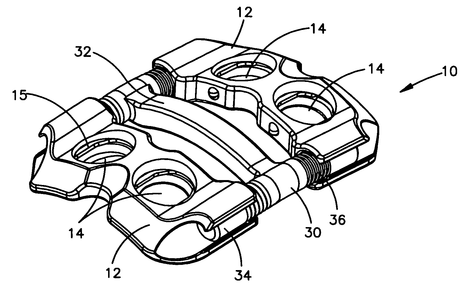
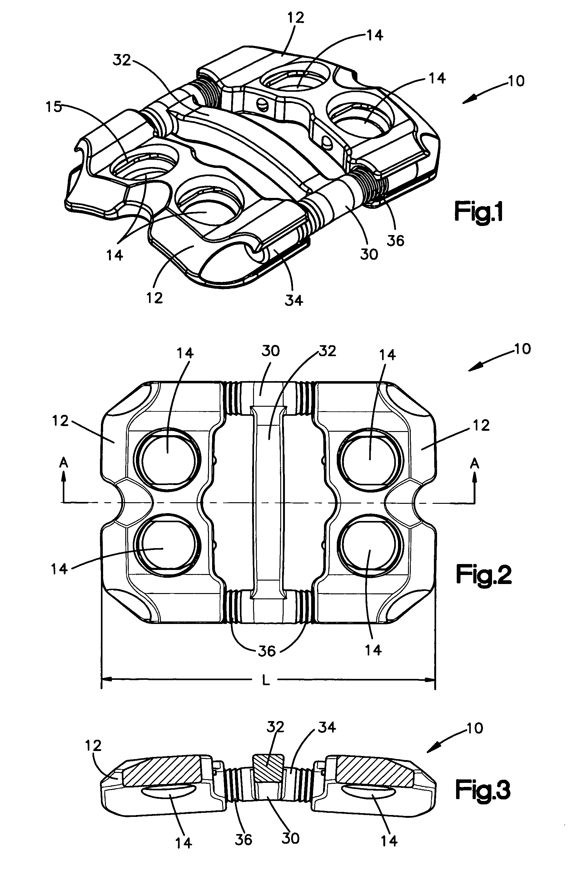
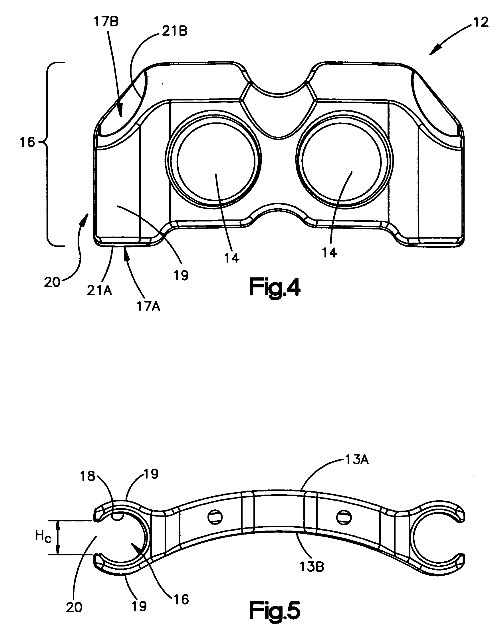
[0037] The system described herein may be used in spinal fusion procedures in which a damaged or diseased disc (or part of a disc) is removed from between a pair of vertebrae and a spinal fusion spacer is placed between the vertebrae. The carriage elements may be applied to an anterior portion of the affected vertebrae to span the affected disc space, and may be fixed to the vertebrae using bone fasteners. The system may function to maintain the vertebrae aligned during the initial period following fixation in which fusion of the spacer to the adjacent vertebrae occurs. The system may also function to share some of the axial spinal load applied to the fusion spacer to prevent extreme subsidence of the spacer into the vertebral body, such as where the patient has poor bone quality. The system may also act to prevent the spacer from being expelled from the disc space during the initial post-operative period.

[0038] The system may be used for single level (i.e. one-disc) or multiple-le...


PUM


Abstract

A fixation system may comprise at least one carriage element being capable of receiving one or more bone fasteners, the carriage element being mountable on a plate, the plate having an engaging portion for adjustably securing the carriage element to the main plate, the engaging portion allowing translational movement of the carriage plate with respect to the plate in only one axial direction. In one embodiment, the plate includes arms for receiving the carriage element and the carriage element includes channels mountable on the arms, with the engaging portion disposed within the channels. A method of use and kit is also described.

Description

FIELD OF THE INVENTION [0001] This invention relates to the field of fixation devices. More particularly, this invention relates to a fixation system for spines, the fixation system being capable of unidirectional translational adjustment. BACKGROUND OF THE INVENTION [0002] Orthopedic fixation devices such as plates are frequently coupled to bone with fasteners inserted through plate holes. It is known that securing such fasteners to the bone plate, for example through the use of expansion-head screws, can decrease the incidence of loosening of the fixation assembly post-operatively. It is also known that a bushing may be disposed in each plate hole to receive the fastener to permit polyaxial movement so that the fastener may be angulated at a surgeon-selected angle. However, polyaxial movement of fasteners through set plate hole locations only increases attachment alternatives of the fasteners themselves. The plate holes remain fixed in relation to each other and to the longitudina...

Claims


Application Information

Patent Timeline
Patent Type & Authority Applications(United States)
IPC IPC(8): A61F2/30
CPCA61B17/7059A61B17/8023A61B17/8047A61B17/58A61B17/70A61B17/80A61B17/84
Inventor SUH, SEAN S.RATHBUN, DAVID S.
Owner SYNTHES USA
Why Eureka
Try Eureka