Flexible fastening machine tool

a flexible and fastening technology, applied in the field of flexible fastening machine tools, can solve the problems of limited machine tools, limited machine tools, and extremely heavy machines, and achieve the effects of reducing production costs, improving production efficiency, and improving service li

Active Publication Date: 2012-07-17
GEN ELECTRO MECHANICAL
View PDF26 Cites 35 Cited by
  • Summary
  • Abstract
  • Description
  • Claims
  • Application Information

AI Technical Summary

Benefits of technology

[0005]The present flexible fastening machine tool comprises first and second facing pedestals mounted on first and second pairs of rails. The first pair of rails is mounted to the floor. The pedestals are movable along the first and second pairs of rails in the Y-axis direction. The second pair of rails is mounted on a rail base, and the second pair of rails extend from the rail base. A third pair of rails is mounted on the floor, and the third pair of rails extend in the X-axis direction. The rail base supporting the second pair of rails is positioned on the third pair of rails, such that the second pedestal is capable of being moved along the third pair of rails in the X-axis direction toward and away from the first pedestal, in addition to being movable in the Y-axis direction. A first movable carriage mounted on the first pedestal and a second carriage mounted on the second pedestal, and a fixture frame, also referred to herein as a frame member, is supported by the first and second carriages. The fixture frame supports a workpiece. The first and second carriages are independently movable toward and away from the first and second pairs of rails such that the frame member is capable of being raised, lowered and tilted. A C-frame is mounted on the third pair of rails, and the C-frame is for performing tooling operations on the workpiece. The flexible fastening machine tool is capable of accommodating differently sized fixture frames, such that a plurality of workpieces may be machined by the same machine tool. Thus, the need for a plurality of machine tools is advantageously eliminated.

Problems solved by technology

These machines are extremely heavy and are housed in very large buildings.
However, the machine tool 8 has limitations.
In addition, the machine tool 8 is limited to the extent that it may only accommodate a dedicated work frame 11 having a fixed length.
This duplication of differently sized machine tools 8 undesirably adds to costs, increases the possibility of down time, increases maintenance costs, and may result in production inefficiencies.

Method used


Image

  • Flexible fastening machine tool
  • Flexible fastening machine tool
  • Flexible fastening machine tool

Examples


Embodiment Construction

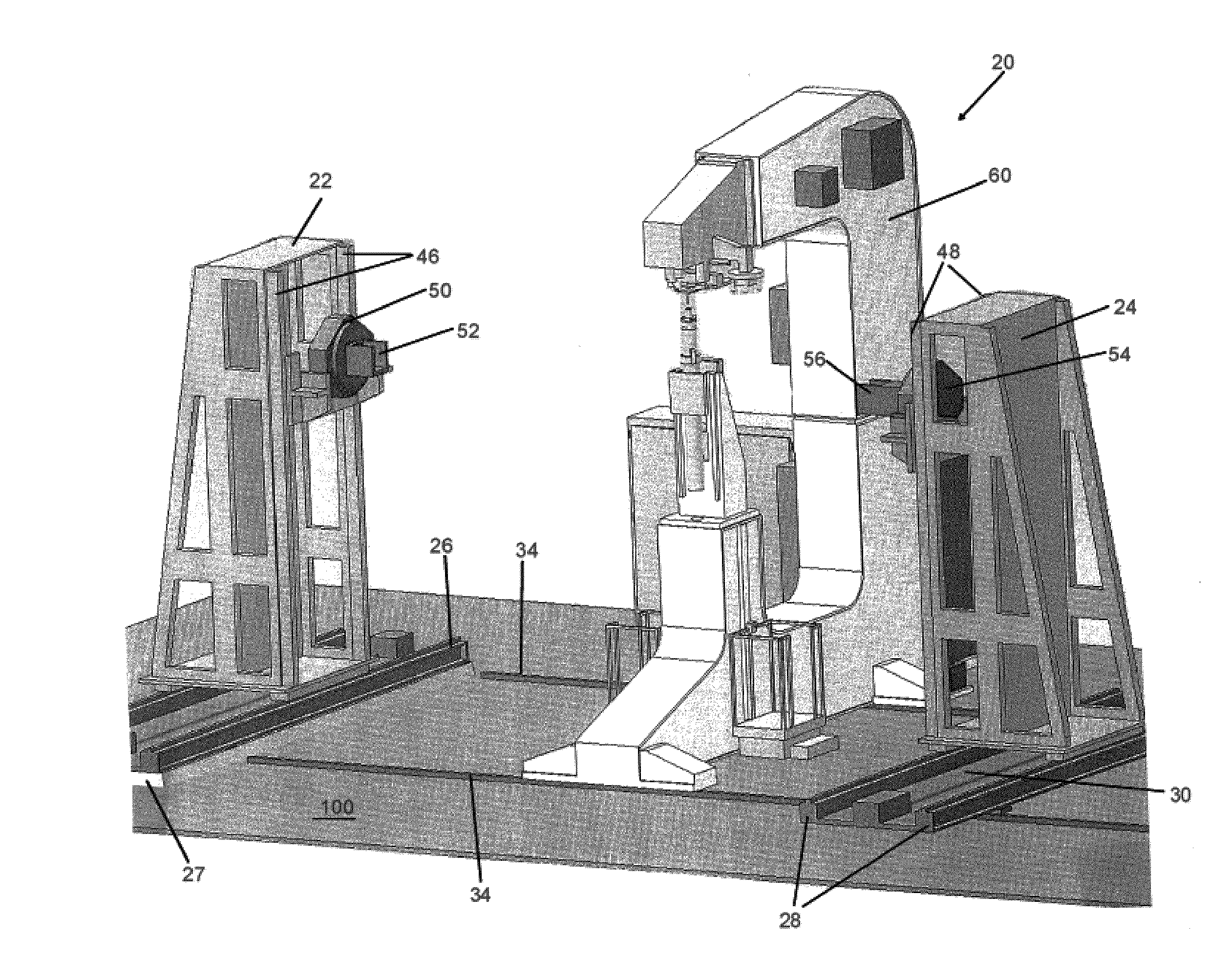
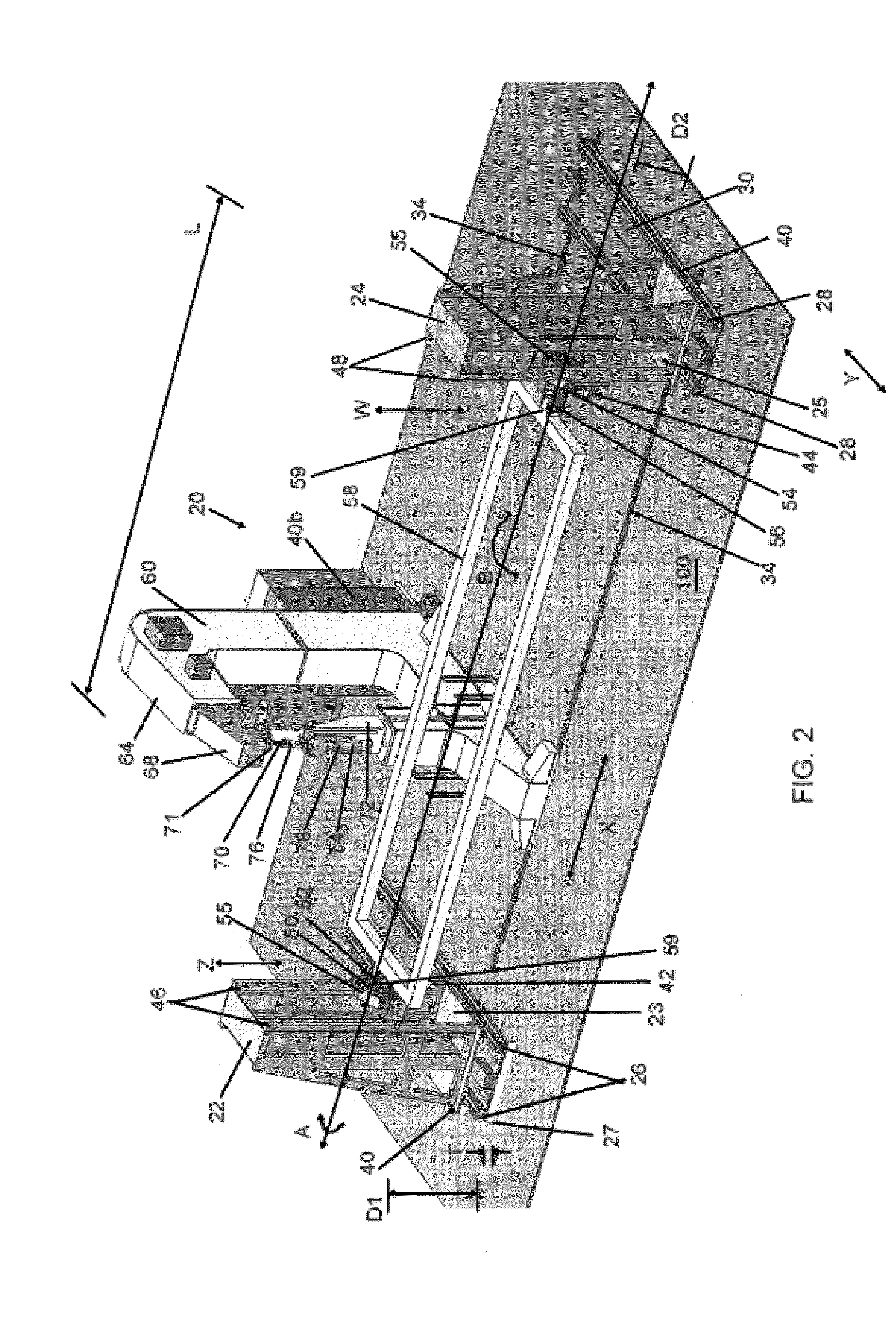
[0018]The present invention is a flexible fastening machine tool 20, as shown in FIGS. 2-15. The flexible fastening machine tool 20 as shown in FIG. 2 comprises first and second pedestals 22, 24, respectively, that face one another. The first pedestal 22 has a first base member 23, and the first base member 23 of the first pedestal 22 is movably positioned on a first pair of rails 26 (also referred to herein as guides 26). The first pair of rails 26 are positioned on a platform 27 and are connected to the platform 27. The platform 27 is supported on the floor or ground 100 of, for example, a factory, and the platform 27 is connected to the floor 100. The second pedestal 24 has a second base member 25, and the second base member 25 is movably positioned on a second pair of rails 28. The first and second pairs of rails 26, 28 are substantially parallel to one another. In other preferred embodiments, each of the first and second base members 23, 25, may be movably positioned on a singl...


PUM

PropertyMeasurementUnit
lengthaaaaaaaaaa
flexibleaaaaaaaaaa
weightaaaaaaaaaa

Abstract

A flexible fastening machine tool having first and second facing pedestals is mounted on first and second pairs of rails. The pedestals are movable along the rails in a Y-axis direction. A rail base is provided and the second pair of rails is mounted on the rail base. A third pair of rails that extend in an X-axis direction are mounted to the floor, and the rail base is positioned on the third pair of rails, such that the second pedestal is movable along the third pair of rails in the X-axis direction toward and away from the first pedestal. A first movable carriage is mounted on the first pedestal and a second movable carriage is mounted on the second pedestal. A frame member is supported by the first and second carriages and the frame member holds a workpiece. The first and second carriages are independently movable toward and away from the first and second pairs of rails such that the fixture frame is capable of being raised, lowered and tilted. A C-frame is mounted on the third pair of rails and the C-frame is capable of performing tooling operations on the workpiece.

Description

CROSS-REFERENCE TO RELATED APPLICATION[0001]The present application claims priority benefit of U.S. Provisional Patent Application No. 61 / 060,949 entitled “Flexible Fastening Machine Tool” filed on Jun. 12, 2008, which is hereby incorporated by reference.BACKGROUND[0002]The components of airplanes, for example the wings and fuselage, are presently manufactured on very large tooling machines. These machines are extremely heavy and are housed in very large buildings. In addition, a plurality of machines are required in order to manufacture a single component of the airplane, because most of the machine tools are dedicated to a specific component.[0003]FIG. 1 is a perspective view of a prior art machine tool 8. There are facing pedestals 10 that are fixed to the shop floor 100. Each of the pedestals 10 supports an end of a very large and heavy work frame 11. The work frame 11 may weigh tens of thousands of pounds. There is a fixture 12 attached to the work frame 11, and a workpiece 14 ...

Claims


Application Information

Patent Timeline
Patent Type & Authority Patents(United States)
IPC IPC(8): B23Q7/00B21J15/10B23C1/00
CPCB21J15/14B21J15/142B23B41/006B23Q1/525B23Q1/623B23Q1/015B23B2215/04B23P2700/01Y10T29/49998Y10T29/5176Y10T29/5177Y10T29/49947
Inventor BURNS, THOMAS E.RIEHLE, GARYDARLAK, EUGENE T.MATHEIS, STEVEN J.
Owner GEN ELECTRO MECHANICAL
Why Eureka
Try Eureka