Optical relay system and network control device

a relay system and network control technology, applied in the field of optical relay systems, can solve the problems of inability to determine the location of the regenerative repeater in the new path, the quality of the optical signal to deteriorate, and the inability to decode the received signal, so as to achieve the effect of reducing the waste of power consumption of the entire optical relay system and low level

Inactive Publication Date: 2013-03-05
HITACHI LTD
View PDF14 Cites 9 Cited by
  • Summary
  • Abstract
  • Description
  • Claims
  • Application Information

AI Technical Summary

Benefits of technology

[0007]Further, there is an idea of constantly regenerating the optical signal by using all the relay devices all of which are provided with regenerative repeaters in order to handle all kinds of path change, but the regeneration may be performed even in a situation in which the regeneration is unnecessary, which leads to wasteful power consumption of the regenerative repeater. In addition, a plurality of optical signals having multiplexed wavelengths pass through each of the relay devices, and hence the wasteful power consumption increases when the regenerative repeaters for all the wavelengths are constantly operated on all the relay devices.
[0008]The present invention has been made in view of the above-mentioned circumstances, and an object of the present invention is to suppress wasteful power consumption of an entire optical relay system to a low level by operating a regenerative repeater when an optical signal needs to be regenerated.
[0029]According to the present application, by operating the regenerative repeater when the optical signal needs to be regenerated, it is possible to suppress wasteful power consumption of the entire optical relay system to a low level.

Problems solved by technology

However, according to the technology disclosed in Patent Document 1, when the path of the optical signal is changed from an initial stage in which an optical network is built, there may be a case where there is a change in a distance by which the optical signal is transmitted without the intermediation of the regenerative repeater, which causes quality of the optical signal to deteriorate, and hence the received signal cannot be decoded.
It cannot be decided where to locate the regenerative repeater in the new path without examining deterioration degrees of signal quality within respective relay devices.
Therefore, even when the wavelength selective switch is used to rapidly switch a relay path of the optical signal, there is no guarantee that the optical signal is appropriately transmitted in the path after the change until completion of the examination of the deterioration degrees of the signal quality within the respective relay devices, and hence it is impossible to gain an advantage that the wavelength selective switch facilitates path switching.
Further, there is an idea of constantly regenerating the optical signal by using all the relay devices all of which are provided with regenerative repeaters in order to handle all kinds of path change, but the regeneration may be performed even in a situation in which the regeneration is unnecessary, which leads to wasteful power consumption of the regenerative repeater.
In addition, a plurality of optical signals having multiplexed wavelengths pass through each of the relay devices, and hence the wasteful power consumption increases when the regenerative repeaters for all the wavelengths are constantly operated on all the relay devices.

Method used


Image

  • Optical relay system and network control device
  • Optical relay system and network control device
  • Optical relay system and network control device

Examples


Embodiment Construction

[0053]Hereinafter, an embodiment of the present invention is described with reference to the accompanying drawings.

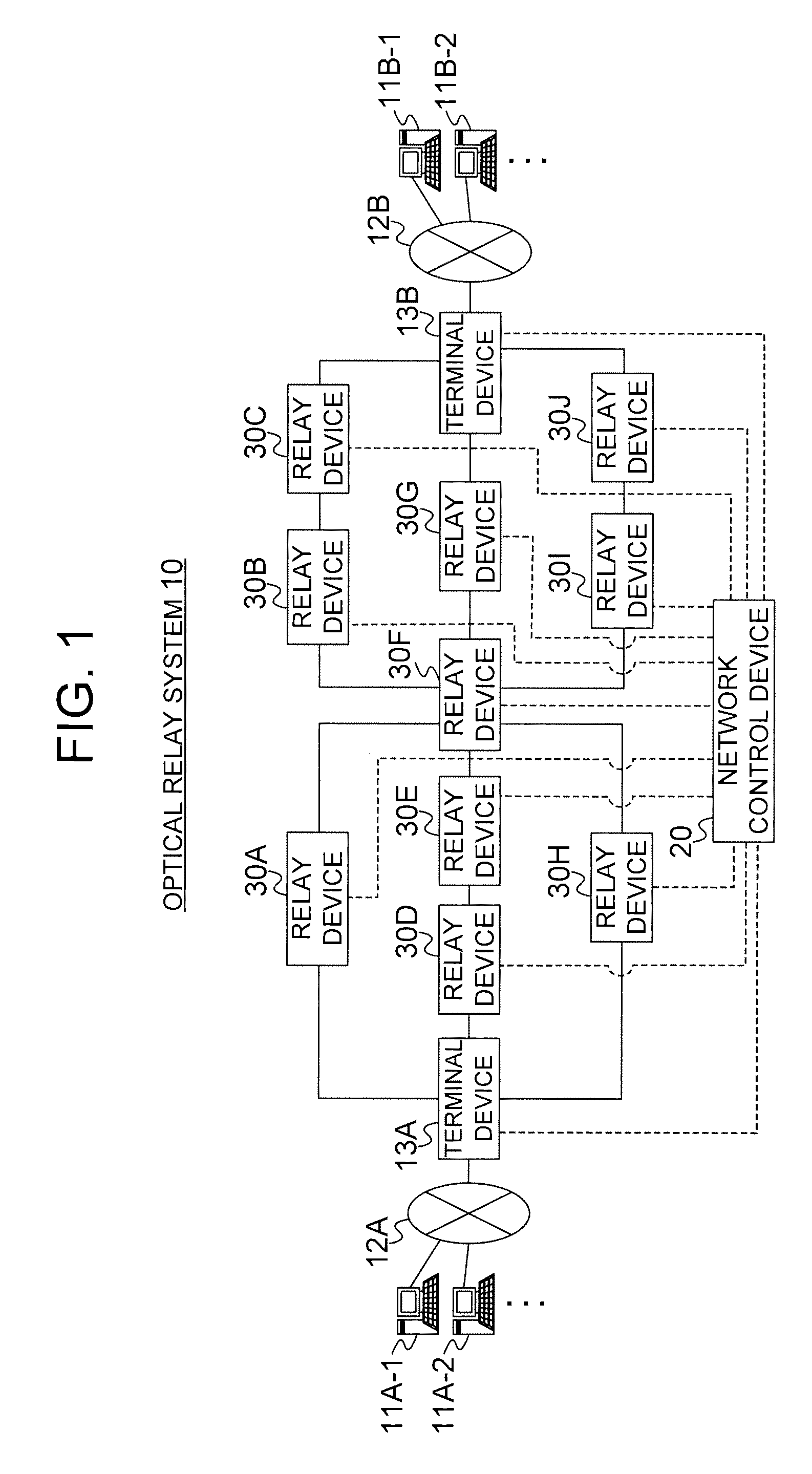
[0054]FIG. 1 is a system configuration diagram illustrating a configuration of an optical relay system 10 according to the embodiment of the present invention. The optical relay system 10 includes a plurality of terminal devices 13, a plurality of relay devices 30, and a network control device 20 which controls the respective relay devices 30.

[0055]The respective terminal devices 13 are, for example, connected to a plurality of communication devices 11 via access lines 12 such as metal cables. Further, the plurality of relay devices 30 are provided between the terminal devices 13, and optical fiber cables are used for connections between the terminal device 13 and the relay device 30 and between the relay device 30 and the relay device 30. Further, the respective terminal devices 13 and the respective relay devices 30 communicate with the network control device 20 via a...


PUM


Abstract

Provided is an optical relay system (10) which is capable of suppressing wasteful power consumption of an entire system to a low level. The optical relay system (10) includes a plurality of relay devices (30) and a network control device (20). The network control device (20) causes an optical signal to be regenerated by a regenerative repeater (35) within the relay device (30) existing at an upstream of the relay device (30) reporting that the optical signal has deteriorated by a degree exceeding a predetermined level. Further, the network control device (20) causes the regenerative repeater (35) to stop regenerating the signal in a case where deterioration of the signal remains within an allowable range even when the regenerative repeater (35) stops regenerating the signal.

Description

CROSS-REFERENCE TO RELATED APPLICATION[0001]The present application claims priority from Japanese application JP 2010-130893 filed on (Jun. 8, 2010), the content of which is hereby incorporated by reference into this application.BACKGROUND OF THE INVENTION[0002]The present application relates to an optical relay system which relays an optical signal by wavelength division multiplexing.[0003]An optical add / drop multiplexer (OADM) which adds / drops a partial wavelength of a plurality of wavelengths that are multiplexed is introduced into a node device within an optical network which uses wavelength division multiplexing (WDM). Further, in recent years, introduction of a wavelength selective switch (WSS) is underway as a device capable of switching a path of an optical signal having an arbitrary wavelength. By building a network using the wavelength selective switch, it is possible to easily change the path of the optical signal even in the network configured only by the optical signal....

Claims


Application Information

Patent Timeline
Patent Type & Authority Patents(United States)
IPC IPC(8): H04J14/00H04B10/07H04B10/27H04B10/29H04J14/02H04L12/24H04M7/00H04Q3/52
CPCH04B10/0797H04B10/29H04J14/0227H04J14/0284H04J14/0212H04J14/0258H04J14/0269H04J14/0275H04J14/0271
Inventor IWASAWA, TAKUYANODA, KENTASUZUKI, TAKAYUKI
Owner HITACHI LTD
Why Eureka
Try Eureka