Condensing boiler employing evaporation device

a technology of condensing boiler and evaporation device, which is applied in the field of condensing boiler, can solve the problems of inability to install a condensing boiler in the field without a condensate drainage processing facility, high energy consumption of the boiler, and inability to obtain high-temperature heating water, so as to maximize the surface area of the filter, reduce energy, and improve the absorption and removal efficiency of the condensate

Active Publication Date: 2019-09-05
KYUNGDONG NAVIEN
View PDF0 Cites 0 Cited by
  • Summary
  • Abstract
  • Description
  • Claims
  • Application Information

AI Technical Summary

Benefits of technology

[0028]According to a condensing boiler configured to employ an evaporation device according to the present invention, since condensate generated in a latent heat exchanger is removed using an evaporation device, the condensing boiler can be installed in the field without a condensate drainage processing facility to reduce energy.
[0029]Further, since an evaporative humidifier formed with a corrugated structure is employed in the evaporation device, absorption and removal efficiency of the condensate can be improved by maximizing a surface area of a filter, and a static pressure can be lowered by sufficiently securing a flow space through which combustion gas passes, and thus additional power consumption can be prevented by minimizing the load of a blower.
[0030]In addition, since the evaporative humidifier is formed of a cellulose material, the removal efficiency of the condensate can be improved by further improving moisture storing performance and a spreading characteristic of water, and since a particle of vapor evaporated from the filter becomes very small unlike a case in which an ultrasonic humidification module of the related art is employed, reintroduction of the condensate in a droplet state can be prevented and contaminated dust or bacteria in the evaporation device can be smoothly discharged.
[0031]In addition, since a water level sensor capable of sensing the remaining condensate is provided, an alert is issued when a high water level is sensed, and when a lower water level due to reduction of the condensate is not sensed, wasted power consumption can be prevented by stopping an operation of the blower.
[0032]In addition, since the blower is additionally operated for a set time even when the lower water level due to the reduction of the condensate is not sensed, moisture which remains in the filter can be also removed.
[0033]In addition, since a temperature sensor configured to sense a temperature of the condensate is provided, when the temperature of the condensate is lower than or equal to a set temperature in winter, the boiler can be prevented from freezing and bursting by allowing a combustion operation to be performed in a burner and operating the boiler with a minimal heat quantity.

Problems solved by technology

Since a heat exchanger of an initial boiler uses only sensible heat generated during combustion of a burner and intactly discharges high-temperature combustion gas through a discharge duct, heat efficiency of the boiler is very low and a great deal of time is consumed to obtain high-temperature heating water.
Since the above-described condensing boiler according to the related art is formed in a structure in which the condensate collector configured to collect the condensate and drain the condensate to the outside and a condensate drain port are formed, the condensing boiler cannot be installed in the field without a condensate drainage processing facility.
Further, in the condensing boiler according to the related art, since an operation of the boiler is stopped due to a drainage failure of the condensate which is frozen in winter, inconvenience and complaints of consumers are caused.
In addition, although the boiler includes a siphon having a U-shaped trap structure to prevent an outflow of the combustion gas to the room therein, the condensate drain port is frequently blocked by foreign matter generated in the heat exchanger or the like.
However, according to the configuration in which an ultrasonic humidifier is applied like the above to remove the condensate, power consumption significantly increases, durability is low, and the vibrator should be periodically managed and replaced.

Method used


Image

  • Condensing boiler employing evaporation device
  • Condensing boiler employing evaporation device
  • Condensing boiler employing evaporation device

Examples


Embodiment Construction

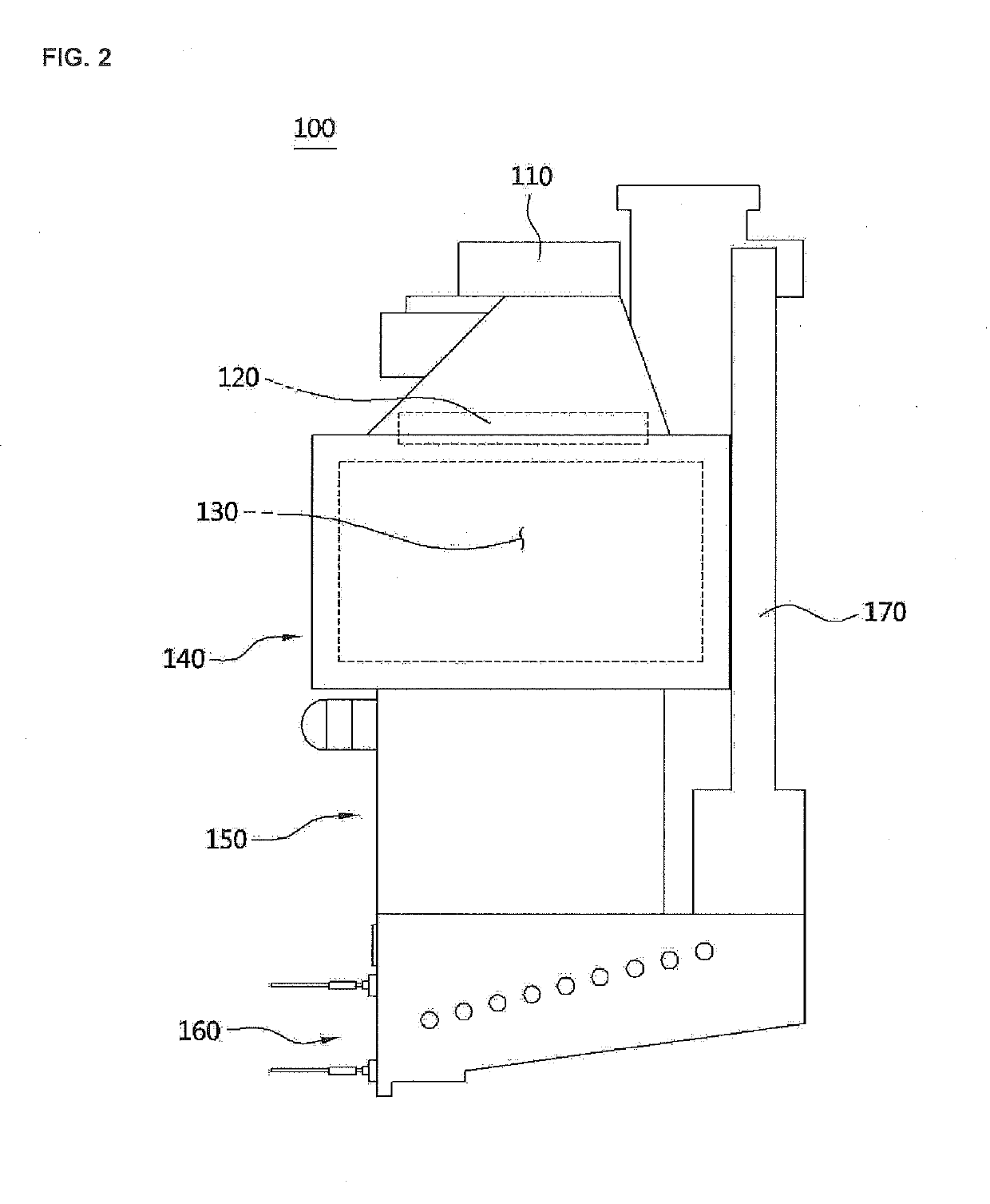
[0043]Hereinafter, a configuration and an action of an embodiment of the present invention will be described in detail with reference to the accompanying drawings.

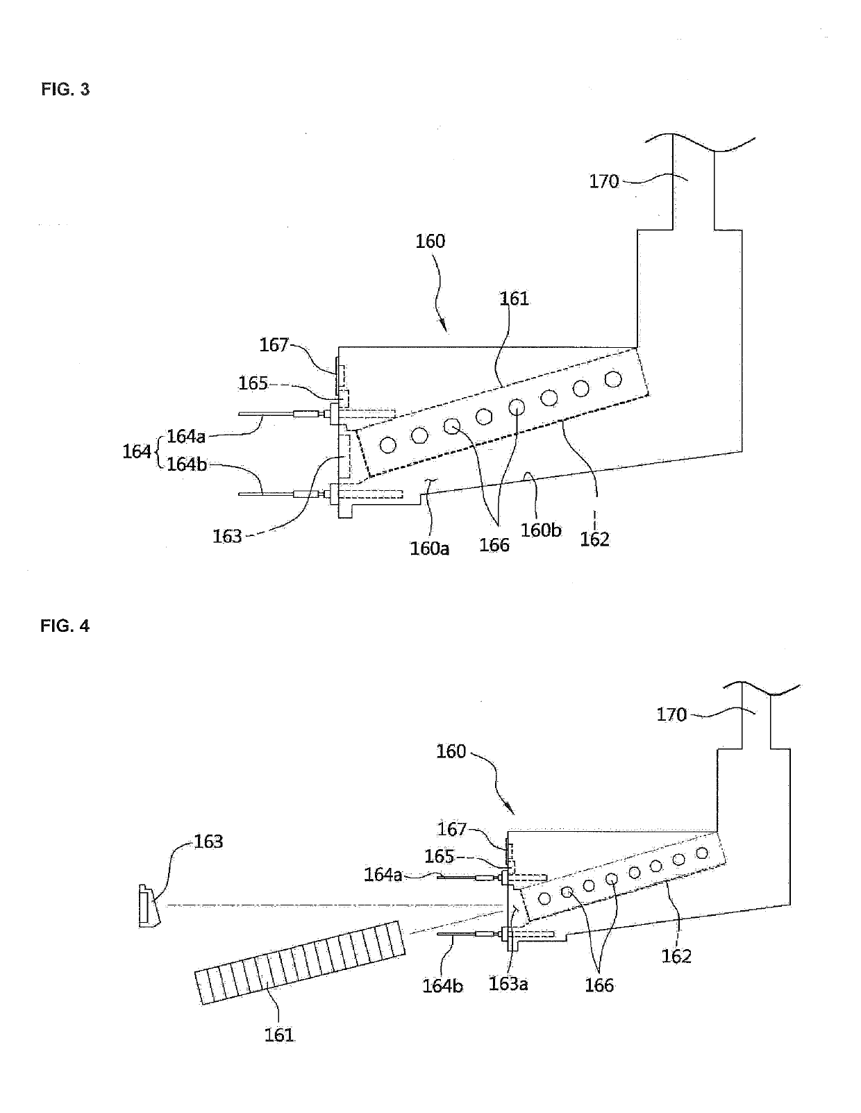
[0044]Referring to FIG. 2, a condensing boiler 100 configured to employ an evaporation device according to the present invention includes a blower 110 configured to supply a supply-air, a burner 120 configured to ignite a fuel-air mixture of combustion gas and the air supplied from the blower 110, a combustion chamber 130 in which the mixture is combusted, a sensible heat exchanger 140 configured to absorb sensible heat of combustion gas generated in the combustion chamber 130 to heat a heat medium, a latent heat exchanger 150 configured to absorb latent heat of vapor included in the combustion gas heat-exchanged in the sensible heat exchanger 140, an evaporation device 160 configured to absorb condensate generated in the latent heat exchanger 150 and evaporate and remove the absorbed condensate using the air supplied from...


PUM


Abstract

The purpose of the present invention is to provide a condensing boiler employing an eco-friendly evaporation device, in which condensed water generated in a latent heat exchanger is removed by using the evaporation device, so that the condensing boiler can be installed in a site without a processing facility for discharging condensed water and contribute to energy saving. For implementation thereof, the present invention comprises: a blower (110) for supplying a supply-air; a sensible heat exchanger (140) for absorbing combustion sensible heat generated in a combustion chamber (130) by combustion by a burner (120); a latent heat exchanger (150) for absorbing latent heat of steam included in combustion gas which has finished heat exchange in the heat sensible exchanger (140); and an evaporation device (160) which absorbs condensed water generated in the latent heat exchanger (150), and has an evaporation type humidifier (161) for evaporating and removing the absorbed condensed water by using air supplied from the blower (110).

Description

TECHNICAL FIELD[0001]The present invention relates to a condensing boiler configured to employ an evaporation device, and more specifically, to a condensing boiler configured to contribute to energy saving and employ an eco-friendly evaporation device by removing condensate using an evaporation device.BACKGROUND ART[0002]A boiler is an apparatus configured to heat a heat medium in a sealed container using a heat source to heat a desired area, and includes a burner configured to combust fuel and a heat exchanger configured to transfer heat from the combusted high-temperature combustion gas to heating water.[0003]Since a heat exchanger of an initial boiler uses only sensible heat generated during combustion of a burner and intactly discharges high-temperature combustion gas through a discharge duct, heat efficiency of the boiler is very low and a great deal of time is consumed to obtain high-temperature heating water.[0004]Accordingly, a recently produced boiler includes a sensible he...

Claims


Application Information

Patent Timeline
Patent Type & Authority Applications(United States)
IPC IPC(8): F24H8/00F24H9/18F24F6/00F24F11/00F24H9/00G01F23/00F24H9/20
CPCF24H8/006F24H9/18F24F6/00F24F11/0008F24F2006/008G01F23/00F24H9/2035F24F2006/006F24H9/0036F24H8/00F24H9/00G01F23/0007Y02B30/00F24F6/043F24H9/1836F24F11/00F24F6/04F24H15/33F24H15/246F24H15/36F24H15/395F24H15/345F24H15/212
Inventor HWANG, IN SOOPARK, JUN KYULEE, KI SEONG
Owner KYUNGDONG NAVIEN
Why Eureka
Try Eureka