
Interference management for distributed antenna systems

a distributed antenna and interference management technology, applied in the field of wireless systems, can solve the problems of unsuitable practical implementation algorithms, exponential increase in complexity of ia algorithms and feedback overhead, and achieve the effect of reducing implementation complexity, reducing complexity, and managing interferen

Inactive Publication Date: 2013-03-05
HITACHI LTD
View PDF11 Cites 5 Cited by
  • Summary
  • Abstract
  • Description
  • Claims
  • Application Information

AI Technical Summary

Benefits of technology

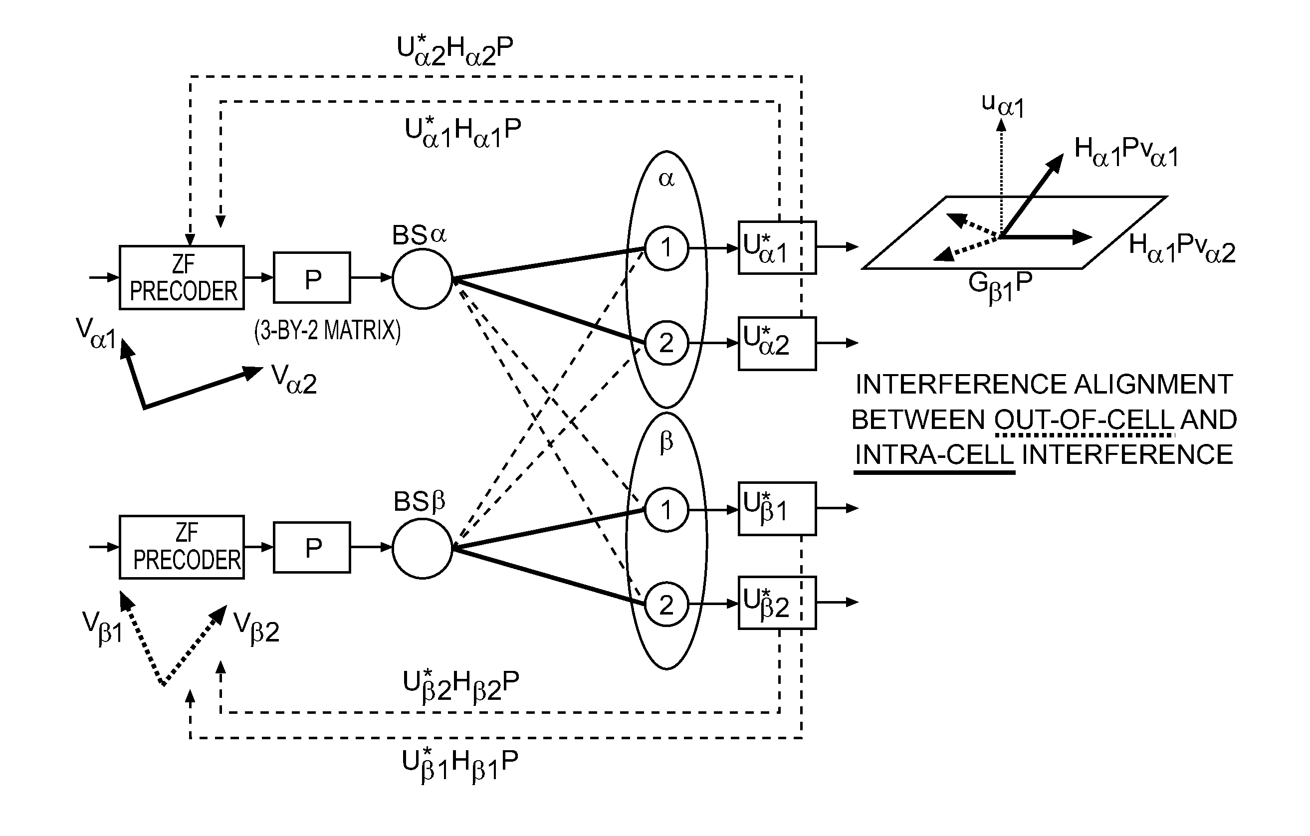
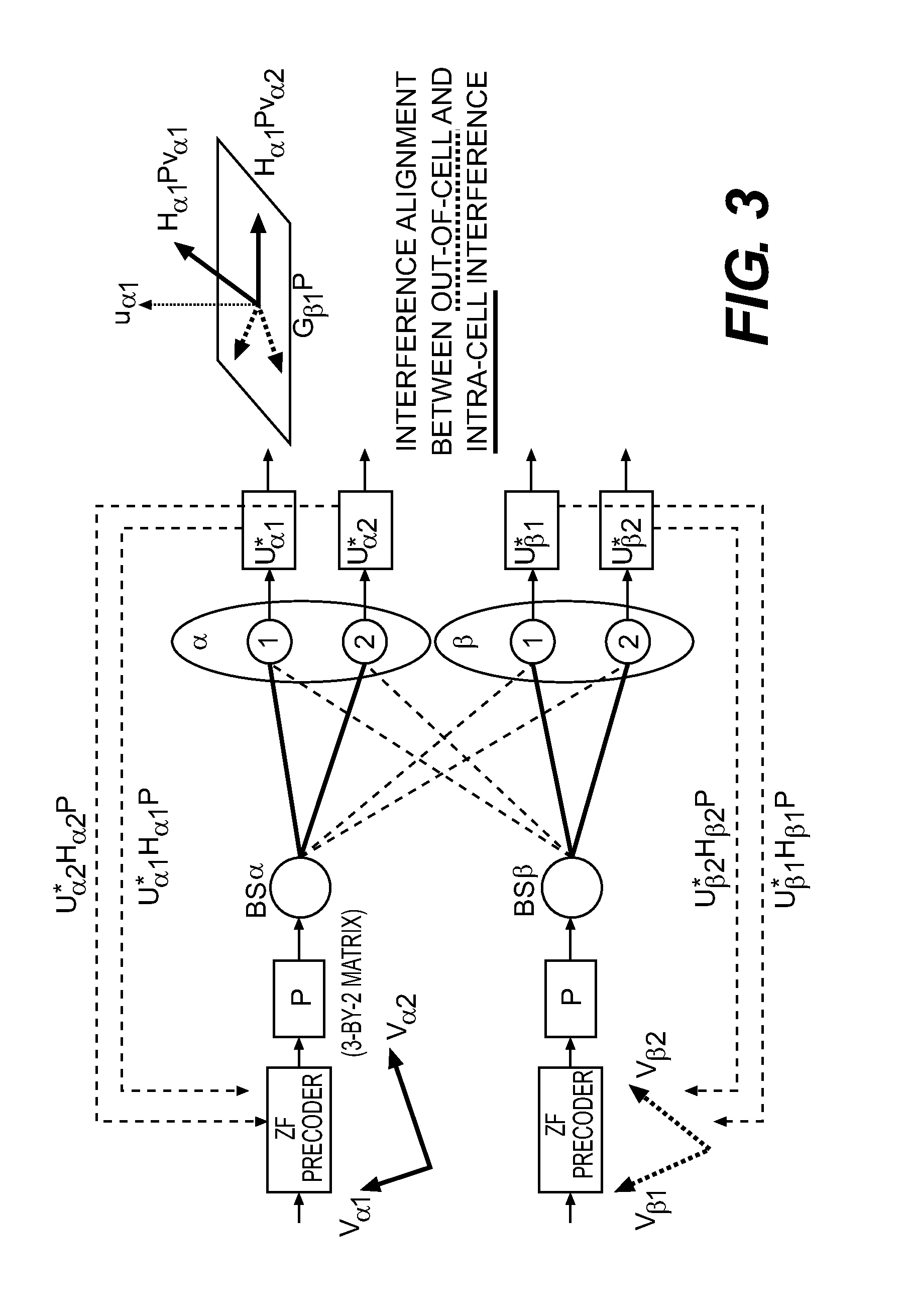
[0006]Exemplary embodiments of the invention provide a way to manage interference in a distributed antenna system. The proposed technique restricts the number of interfering clusters by frequency partitioning and cluster scheduling and subsequently employs interference alignment (IA) to manage the remaining interference. Interference alignment is the key technology which manages inter-cluster interference. As discussed above, although conventional IA algorithms can work for multiple interferers, as the number of interferers increase, the complexity of the IA algorithms and feedback overhead also go up exponentially, rendering the algorithms unsuitable for practical implementation. According to embodiments of this invention, a DAS-based network can be designed to restrict the maximum number of interfering clusters to one. This is achieved via frequency planning or partitioning and cluster scheduling. Moreover, modifications to the conventional IA algorithm are proposed for use in the present system to reduce implementation complexity at the UE.

Problems solved by technology

As discussed above, although conventional IA algorithms can work for multiple interferers, as the number of interferers increase, the complexity of the IA algorithms and feedback overhead also go up exponentially, rendering the algorithms unsuitable for practical implementation.

Method used


Image

  • Interference management for distributed antenna systems
  • Interference management for distributed antenna systems
  • Interference management for distributed antenna systems

Examples


Embodiment Construction

[0027]In the following detailed description of the invention, reference is made to the accompanying drawings which form a part of the disclosure, and in which are shown by way of illustration, and not of limitation, exemplary embodiments by which the invention may be practiced. In the drawings, like numerals describe substantially similar components throughout the several views. Further, it should be noted that while the detailed description provides various exemplary embodiments, as described below and as illustrated in the drawings, the present invention is not limited to the embodiments described and illustrated herein, but can extend to other embodiments, as would be known or as would become known to those skilled in the art. Reference in the specification to “one embodiment,”“this embodiment,” or “these embodiments” means that a particular feature, structure, or characteristic described in connection with the embodiment is included in at least one embodiment of the invention, a...


PUM


Abstract

A central base station for interference management in a distributed antenna system comprises a processor; a memory; and a frequency partition module configured to divide the remote radio heads into clusters and allocate a frequency band to each cluster. Multiple clusters use the same frequency band and groups of clusters are formed. A joint scheduler is configured, for each group, to activate at most two clusters at any given time and deactivate remaining clusters in the group, one of the at most two activated clusters being a serving cluster of the group, and to associate one or more users with the serving cluster in the group. An interference alignment module is configured to apply downlink interference alignment between the at most two activated clusters in each group to align transmit directions of all interferences between the at most two activated clusters.

Description

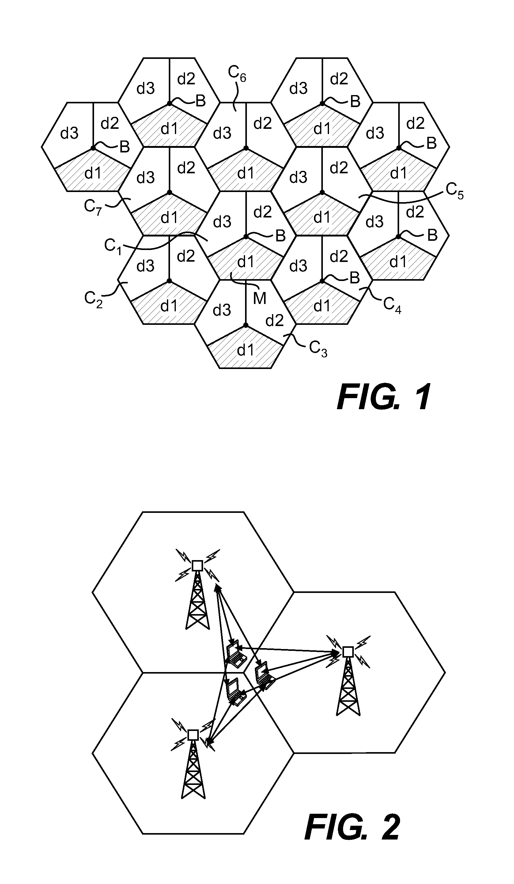
BACKGROUND OF THE INVENTION[0001]The present invention relates generally to wireless systems and, more particularly, to interference management for distributed antenna systems.[0002]In a distributed antenna system (DAS), multiple distributed antennae are set up in a geographical region and are connected via fiber to a centralized Base Station (CBS) which manages these antennae. The antennae are grouped into clusters which serve users (UEs).[0003]Frequency partitioning is a well-known concept used to eliminate inter-cell interference in cellular networks. FIG. 1 shows an example of a cellular network where different sectors of a cell are assigned different frequency bands (d1, d2, d3) so that co-channel interference is minimized at adjacent sectors of different cells. For example, in cell C6, the sector with frequency band “d1” does not have any neighboring sectors operating at the same frequency band. Thus, co-channel interference from neighboring cells is completely eliminated and ...

Claims


Application Information

Patent Timeline
Patent Type & Authority Patents(United States)
IPC IPC(8): H04W40/00
CPCH04W28/16H04W28/04H04W88/085H04W72/12
Inventor GAO, LONGACHARYA, JOYDEEP
Owner HITACHI LTD
Learn More