Method of and apparatus for supporting walls of a power boiler

a technology for supporting walls and power boilers, which is applied in the direction of boiler flue tubes/fire tubes, steam boiler components, liquid fuel feeders, etc., can solve the problems of increasing the weight of supporting structures and the subject of buckstays to considerable stresses, and achieve the effect of lightening buckstays

Active Publication Date: 2013-03-12
FOSTER WHEELER ENERGIA OY
View PDF26 Cites 6 Cited by
  • Summary
  • Abstract
  • Description
  • Claims
  • Application Information

AI Technical Summary

Benefits of technology

[0017]Another advantage of the invention is that the structure in accordance with an advantageous embodiment of the present invention enables the lightening of the buckstays, because the structure does not cause compression or twisting of the buckstay, and, thus, it is not necessary to dimension the buckstays to bear the corresponding loads.
[0018]A third advantage of the invention worth mentioning is that, in an arrangement in accordance with another preferred embodiment of the invention, it is possible to lighten the buckstays further, in such a way that the space between the boiler and the separator can be constructed to be smaller than before, without losing any of the support of the walls.

Problems solved by technology

However, such a water tube wall is, considering its size, relatively light in structure and does not endure additional stresses as such without bending.
Such a suspending of support structures, however, brings about some disadvantages.
Furthermore, when the size of the boilers increases, it is evident that the weight of the supporting structures increases at least in the same ratio.
Another problem encountered is that the buckstays are subjected to considerable stresses, regardless of the manner in accordance with the prior art, by means of which, they are arranged into connection with the boiler walls.

Method used


Image

  • Method of and apparatus for supporting walls of a power boiler
  • Method of and apparatus for supporting walls of a power boiler
  • Method of and apparatus for supporting walls of a power boiler

Examples


Embodiment Construction

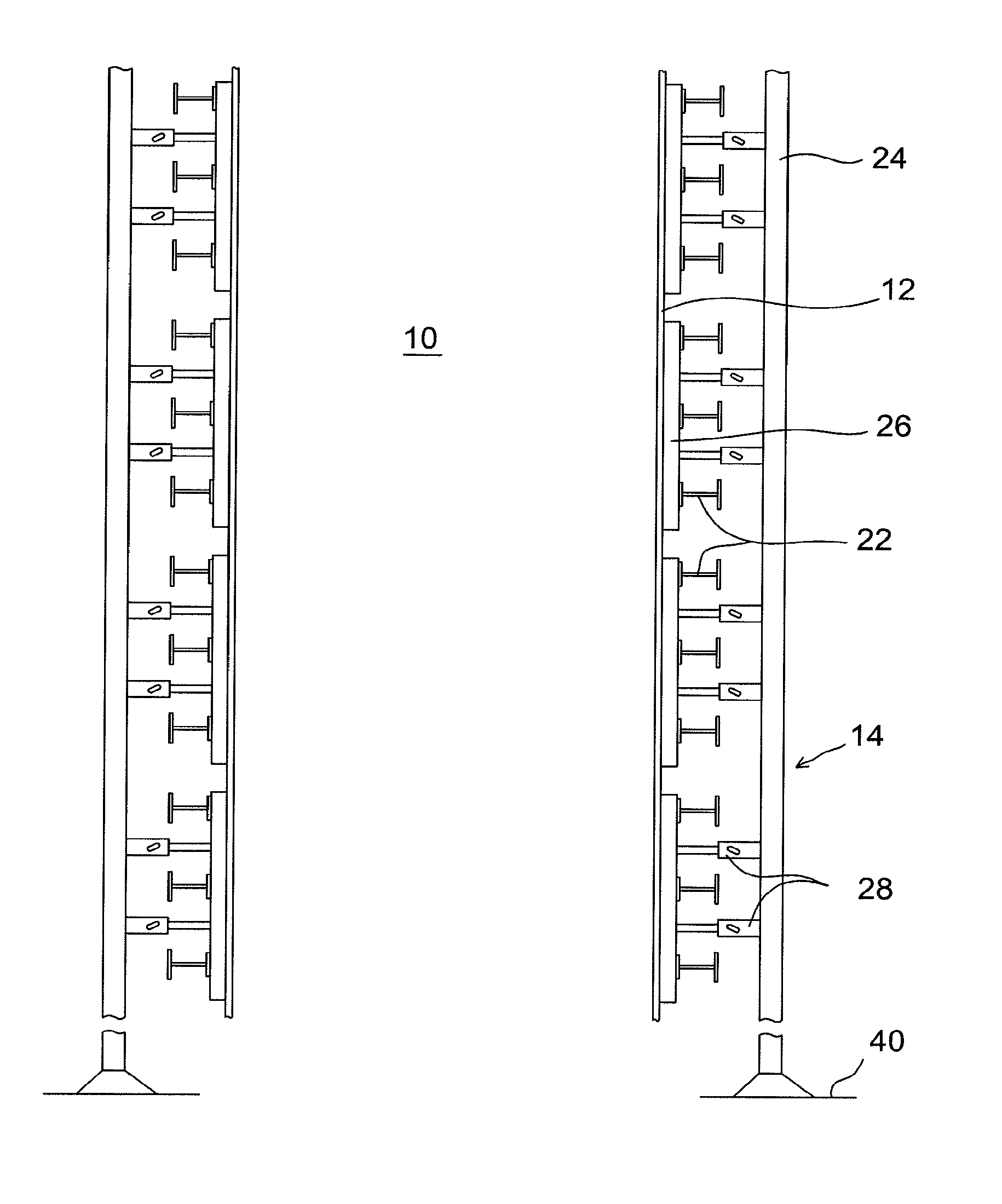
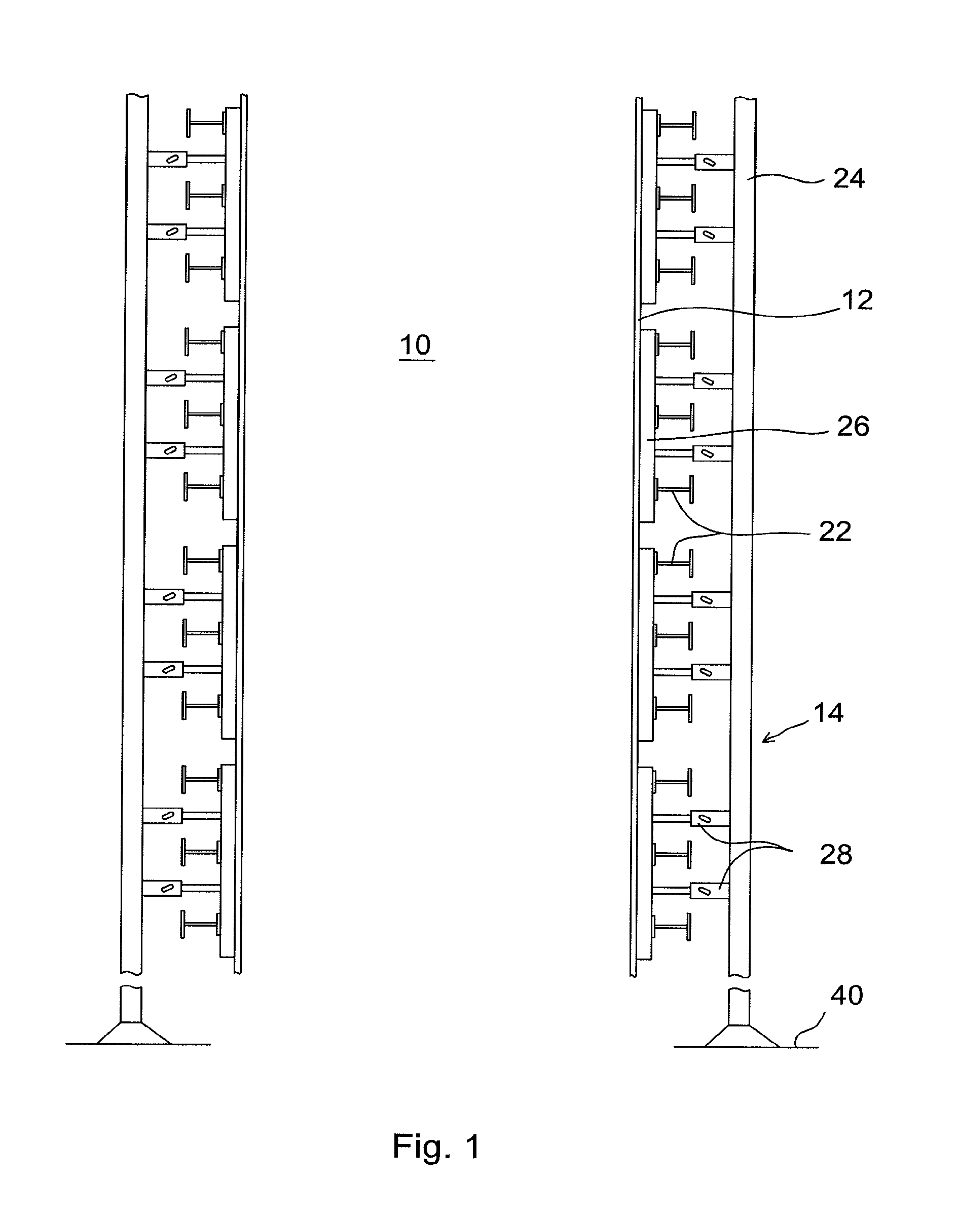
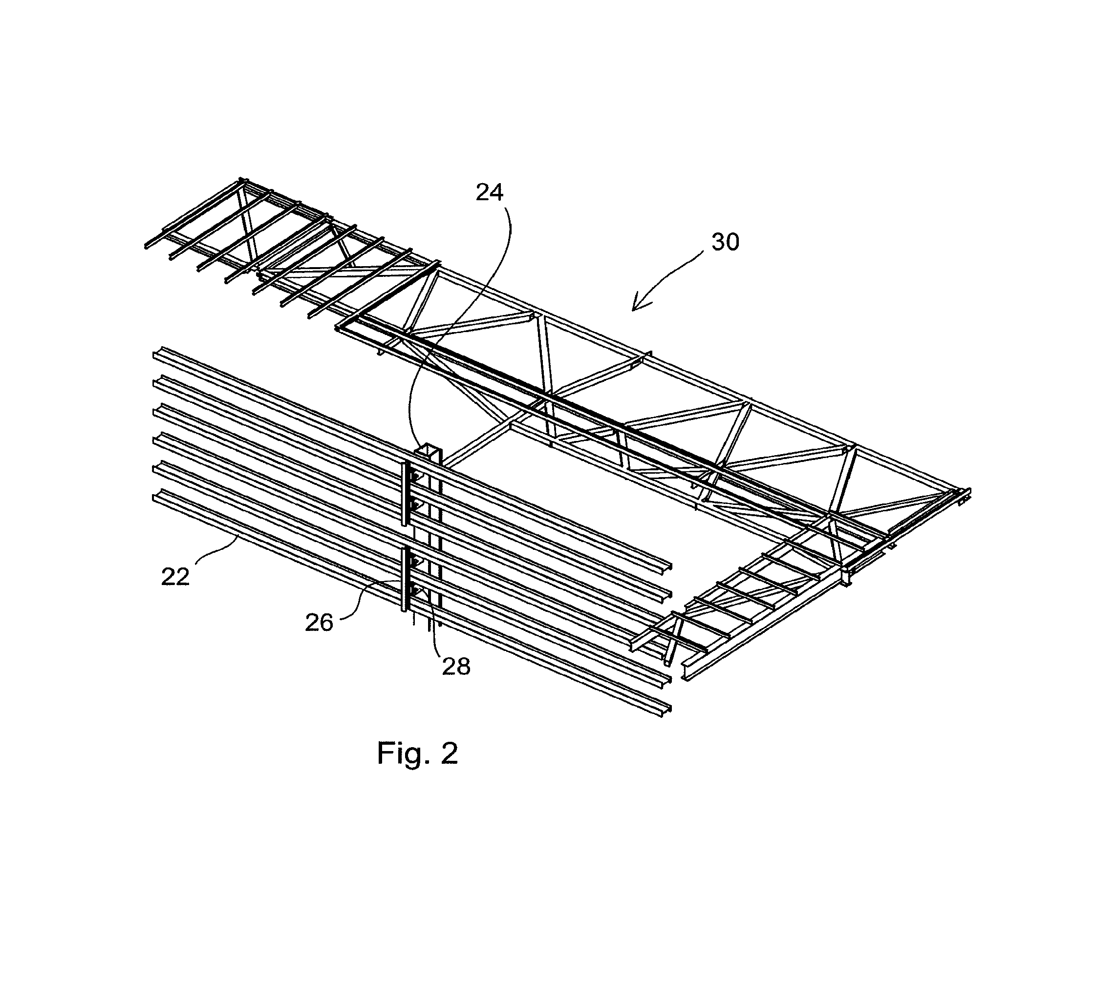
[0023]FIG. 1 schematically illustrates a sectional view of a power boiler, cut of its lower and upper part in such a way that only the central parts of the opposing vertical walls of the boiler are shown. Thus, the drawing shows neither the suspending means of the boiler, nor the channels for the inflowing or outflowing materials. The drawing, thus, shows merely a part of the furnace 10 of the power boiler surrounded by the boiler walls 12, which, in most of the cases, form a rectangle, and means 14 related to the actual supporting of the wall 12. The boiler walls 12 are formed, in the manner known also from the prior art boilers, of water tube panels, in which the vertical water tubes are connected to each other by means of fins parallel to the wall plane. As mentioned above, in connection with the discussion of the prior art, such a water tube wall is supported at the side opposite to the furnace 10 by means of substantially horizontal buckstays, marked with the reference numbers ...


PUM


Abstract

A method of supporting walls of a hanging furnace of a thermal power boiler, in which method, the walls, being formed of vertical water tubes, are supported horizontally at least by means of buckstays, and vertical pillars, located outside the buckstays, are attached to the ground or the foundations of a boiler building. The method includes attaching beams to the outer surface of the water tube walls, parallel with the vertical water tubes of the walls. Buckstays are attached to the outer surface of the beams. The buckstays are positioned substantially perpendicular to the vertical water tubes of the walls. At least two of the walls, located on opposite sides of the furnace, are connected to the vertical pillars by means of the beams and by an attachment connected directly to the beams and to the pillars, in such a way that pressure loads directed perpendicularly to the water tube walls are transferred by means of the vertical pillars to at least one rigid plane surrounding the boiler.

Description

[0001]This application is a U.S. national stage application of PCT International Application No. PCT / FI2006 / 050555, filed Dec. 14, 2006, and published as PCT Publication No. WO 2007 / 068802 A2, and which claims priority from Finnish patent application number 20055674, filed Dec. 15, 2005.FIELD OF THE INVENTION[0002]The present invention relates to a method of and an apparatus for supporting walls of a power boiler. In more detail, the present invention relates to a thermal power boiler, which generally comprises the actual furnace and means for treating flue gases and, in the case of a circulating fluidized bed boiler, also comprises means for circulating bed material and recirculating the material to the furnace. The invention especially relates to supporting panel-structured walls of such a boiler.BACKGROUND OF THE INVENTION[0003]Conventionally, the power boilers of the invention are provided with so-called water tube walls, which consist of adjacent water tubes with plate-like fin...

Claims


Application Information

Patent Timeline
Patent Type & Authority Patents(United States)
IPC IPC(8): F22B37/24F22B
CPCF22B37/244F22B37/208F22B37/00F22B37/20
Inventor LANKINEN, PENTTI
Owner FOSTER WHEELER ENERGIA OY
Why Eureka
Try Eureka