Electronic viscous liquid dispenser

a dispenser and viscous technology, applied in the field of viscous liquid dispensers, can solve the problems of unfavorable operation of the dispenser, needing replacement, unnecessary logistic and manpower resources, etc., and achieve the effect of enhancing structural support and rigidity

Active Publication Date: 2009-05-05
KIMBERLY-CLARK WORLDWIDE INC
View PDF13 Cites 46 Cited by
  • Summary
  • Abstract
  • Description
  • Claims
  • Application Information

AI Technical Summary

Benefits of technology

[0016]The dispensing pump mechanism may take on any number of suitable configurations. In one embodiment, the mechanism includes a linearly slidable cylinder having a delivery channel defined therethrough that terminates in the delivery end. A valve mechanism is disposed in the delivery end of the pump cylinder and is configured to close upon return movement of the cylinder to its rest position to prevent leakage or dripping of liquid from the pump cylinder. The cylinder is slidable within a substantially horizontally disposed pump chamber defined within the reservoir. In one embodiment of the pump mechanism, the pump cylinder is insertable into the pump chamber from its back end. The chamber includes retaining structure, such as a flange member or the like, at its front end to prevent withdrawal of the pump cylinder from the pump chamber through the front end. A cap member or like device is attached to the back end of the pump chamber once the cylinder has been inserted into the chamber. The cap member has an orifice defined therethrough for drawing liquid into the pump chamber. A check valve device, such as a shuttle valve, is disposed in the orifice to close the orifice upon actuation of the pump cylinder.
[0029]As mentioned, the housing structure is preferably formed from a relatively inexpensive molded plastic and may comprise separately molded components that are permanently affixed or adhered to each other. For example, the housing may include a front component that is formed separately from and adhered to a back component. It may be desired that the front and back components have different characteristics. For example, it may be desired that the back component is more rigid than the front component to provide enhanced structural support and rigidity to the dispenser mounted on the wall structure. This may be accomplished by simply making the back component thicker than the front component.

Problems solved by technology

If the housing structure or dosing pump is damaged or vandalized, the dispenser becomes inoperable and must be replaced.
This process entails unnecessary logistic and manpower resources.
However, venting through the pump mechanism may result in undesired leakage through the mechanism, particularly if the pump mechanism is disposed in the lower portion of the housing.

Method used


Image

  • Electronic viscous liquid dispenser
  • Electronic viscous liquid dispenser
  • Electronic viscous liquid dispenser

Examples


Embodiment Construction

[0052]Reference will now be made in detail to embodiments of the invention, one or more examples of which are illustrated in the drawings. Each example is provided by way of explanation of the invention, not meant as a limitation of the invention. For example, features illustrated or described as part of one embodiment, may be used with another embodiment, to yield still a further embodiment. It is intended that the present invention include modifications and variations to the embodiments described herein.

[0053]Various features of the present invention are described in detail in U.S. Pat. Nos. 6,533,145; 6,543,651; 6,575,334; and 6,575,335, all commonly owned by the present assignee, Kimberly-Clark Worldwide, Inc. These patents are incorporated herein in their entirety for all purposes.

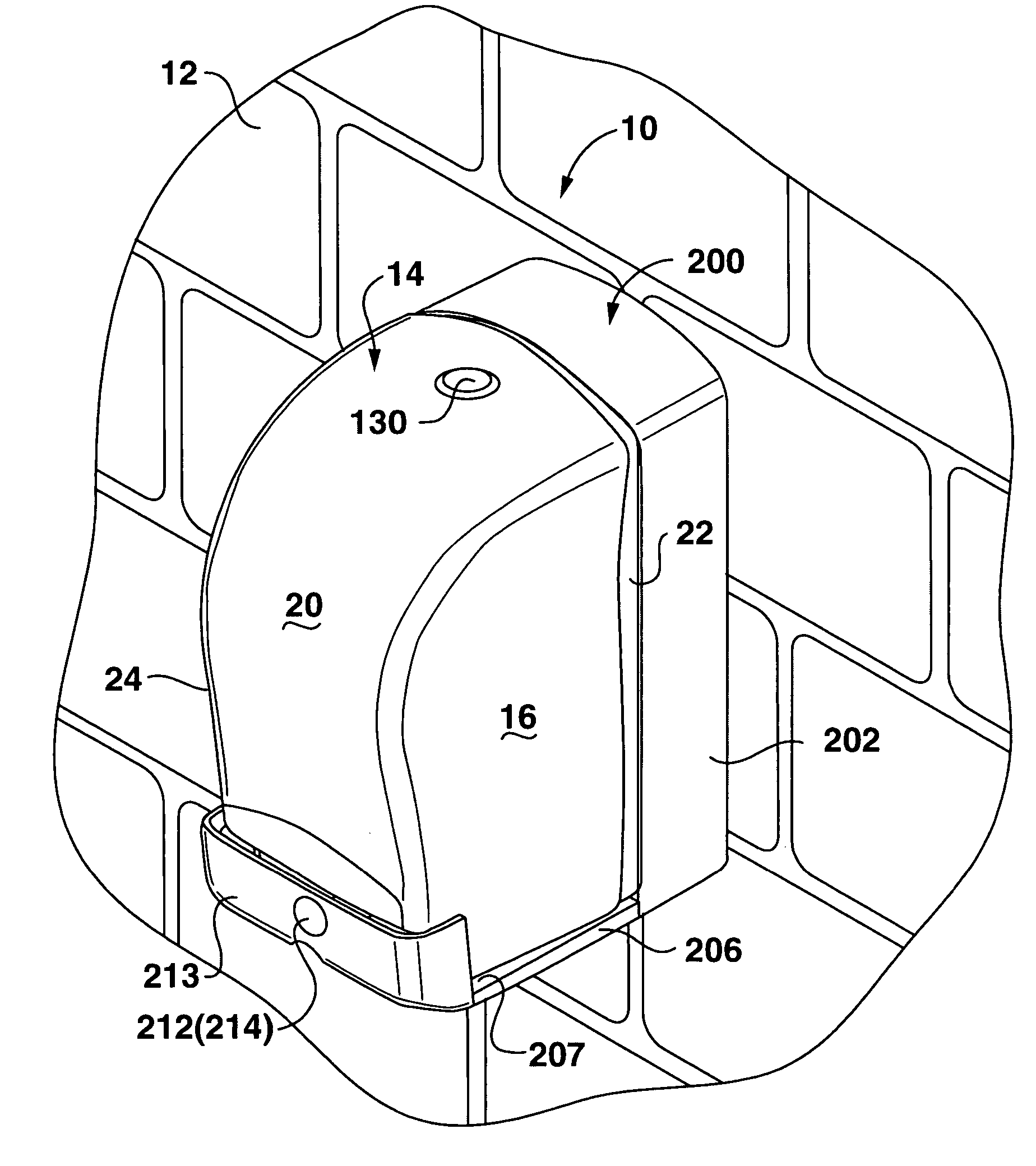
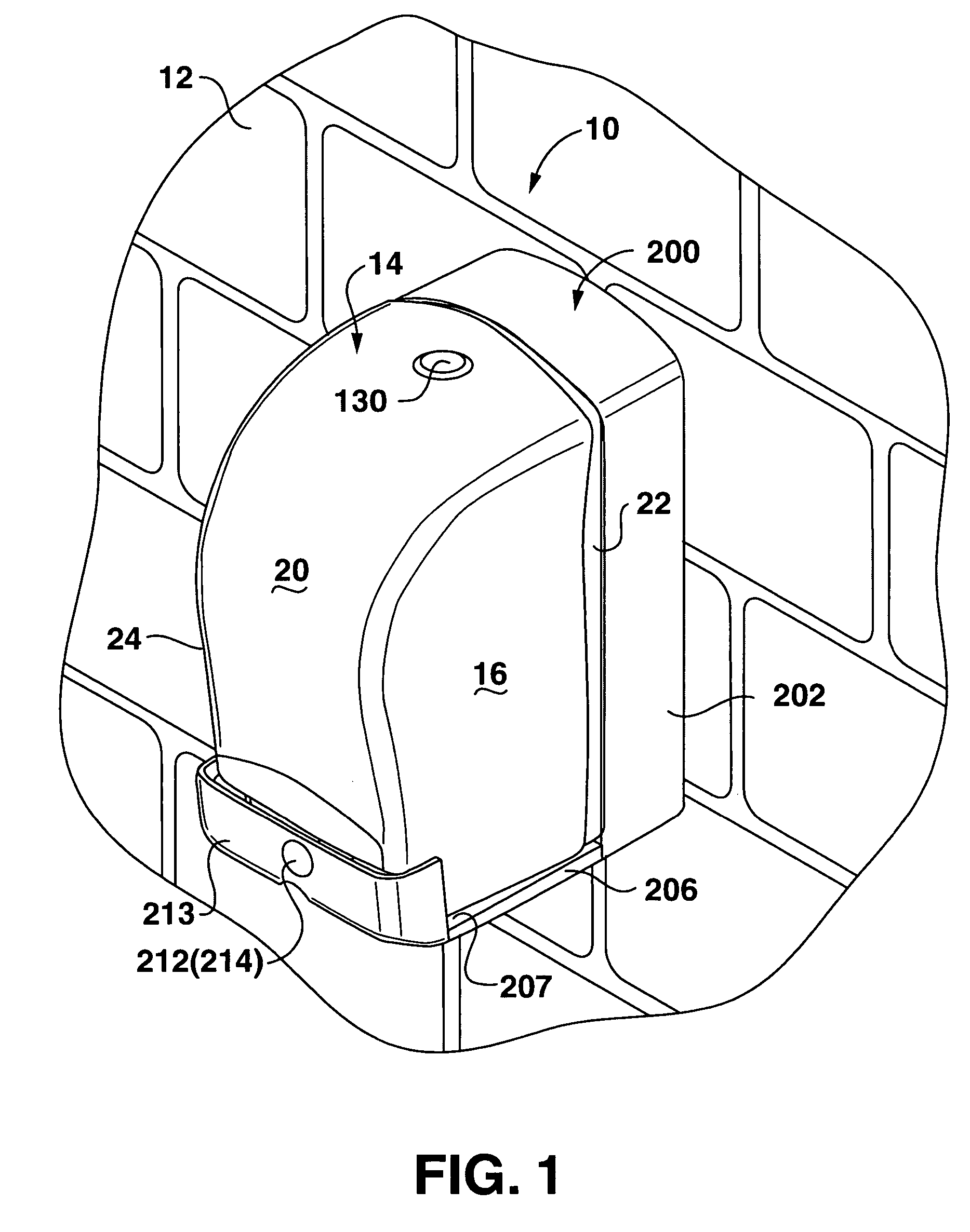
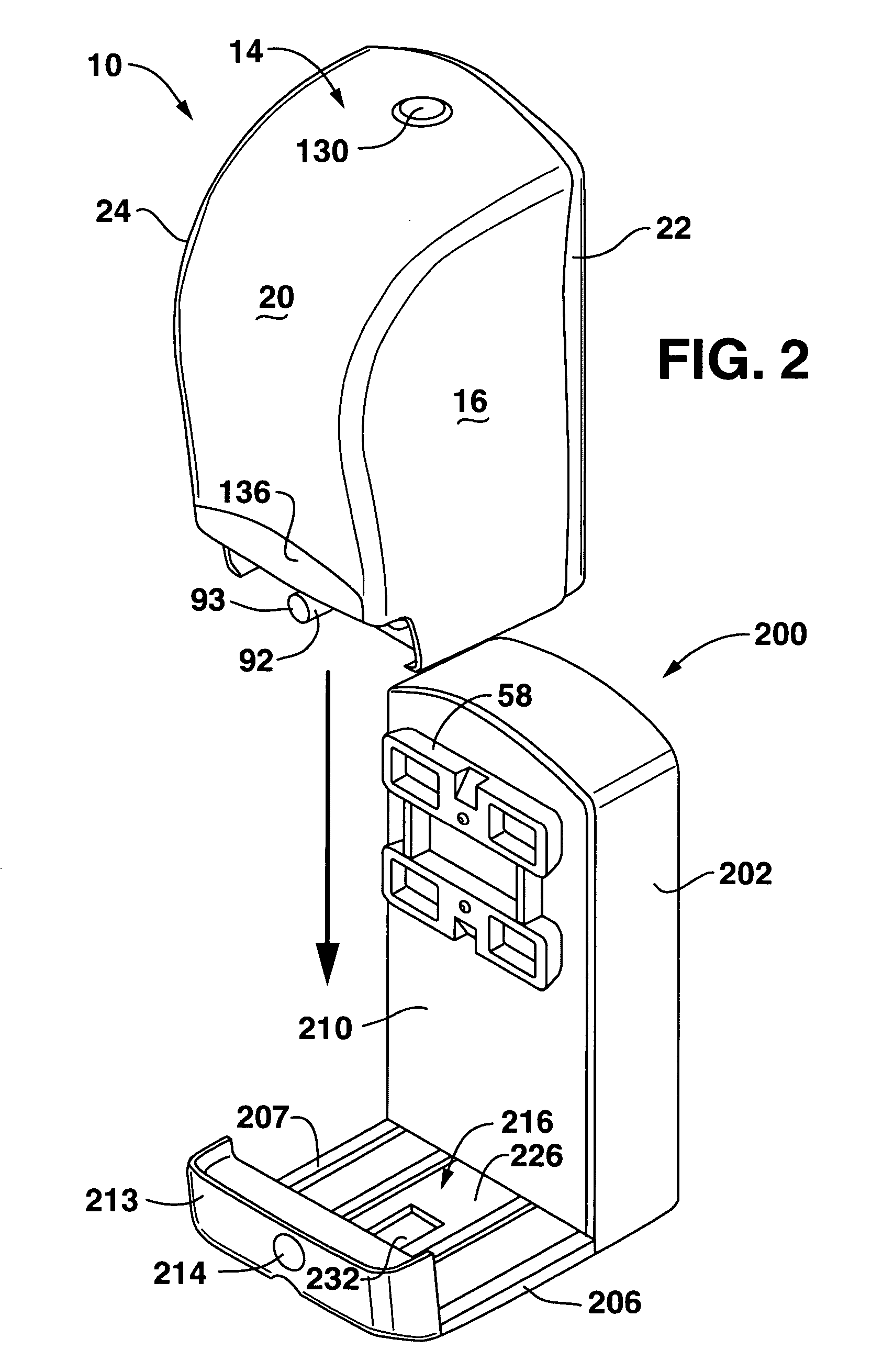
[0054]A viscous liquid dispenser 10 according to the invention is illustrated generally in the figures. The dispenser 10 is illustrated and described herein as a liquid soap dispenser, which is a part...


PUM


Abstract

An electronic self contained viscous liquid dispenser includes a housing defining an internal liquid reservoir. A dispensing pump mechanism is carried by the housing and disposed in liquid communication with the reservoir. The pump mechanism has a delivery end disposed for delivering metered doses of viscous liquid from the reservoir. A mounting assembly is configured for mounting on a supporting wall structure, with the housing being releasably attachable to the mounting assembly. An electronic actuating mechanism is carried by the mounting assembly and includes a motor driven actuator that engages with the pump mechanism upon insertion of the housing into the mounting assembly. A motor and associated power supply circuitry is carried by the mounting assembly, with the motor being in driving engagement with the motor driven actuator.

Description

FIELD OF THE INVENTION[0001]The present invention relates to the field of viscous liquid dispensers, for example soap dispensers, shampoo and lotion dispensers, food product dispensers, and the like.BACKGROUND OF THE INVENTION[0002]Various configurations and models of liquid dispensers, particularly liquid soap dispensers, are well known in the art. Conventional dispensers utilized, for example, in public restrooms and the like, are wall mounted units that typically include a housing structure that is permanently affixed to a wall. These dispensers may include an access door or member so that the dispenser can be opened by a maintenance person for refilling or servicing. With certain types of dispensers, separate refill cartridges are inserted into the housing structure. With other types of dispensers, the maintenance technician must directly refill a reservoir provided in the housing structure. The dispensers typically include a delivery device, such as a dosing pump, and a device ...

Claims


Application Information

Patent Timeline
Patent Type & Authority Patents(United States)
IPC IPC(8): B65D88/54A47K5/12
CPCA47K5/1204A47K5/1217
Inventor LEWIS, RICHARD P.
Owner KIMBERLY-CLARK WORLDWIDE INC
Why Eureka
Try Eureka