System for identifying the position of three-dimensional machine for measuring or machining in a fixed frame of reference

a three-dimensional machine and fixed frame technology, applied in the direction of point-to-point measurements, measurement devices, instruments, etc., can solve the problem of remaining very constrictiv

Active Publication Date: 2008-06-10
ROMER INC
View PDF23 Cites 48 Cited by
  • Summary
  • Abstract
  • Description
  • Claims
  • Application Information

AI Technical Summary

Benefits of technology

[0015]Thus, if the stand of the machine is moved, e.g. by running along the surface of a floor, the multiple-axis assembly with two hinged arms deforms naturally, following the displacement of said stand, and all of the displacements are automatically calculated by using the angle encoders integrated in the multi-axis assembly. This thus provides a follower system that achieves good flexibility.
[0016]Preferably, the first base is secured to the machine stand, and the second base is secured to a horizontal bar, itself secured to a floor surface. In particular, the horizontal bar is arranged to receive a plurality of second bases, and specifically a second base, in the vicinity of each of its ends. Thus, with a workpiece comprising motor vehicle bodywork, it is possible to secure such a bar under the bodywork so that the ends of said bar project beyond the width of said bodywork, thus enabling the multiple-axis assembly to be put into place very quickly on one side or the other of the bodywork.
[0020]It is also advantageous to make provision for the connections between each central segment and the associated arm segments to be via quick-release couplings, and for the connection between each end fork and the associated endpiece to be a quick-release screw connection.

Problems solved by technology

The above systems are entirely satisfactory in terms of accuracy, but they remain very constricting when the machining or measurement machine needs to be moved frequently relative to the article being measured, in particular motor vehicle bodywork.

Method used


Image

  • System for identifying the position of three-dimensional machine for measuring or machining in a fixed frame of reference
  • System for identifying the position of three-dimensional machine for measuring or machining in a fixed frame of reference
  • System for identifying the position of three-dimensional machine for measuring or machining in a fixed frame of reference

Examples


Embodiment Construction

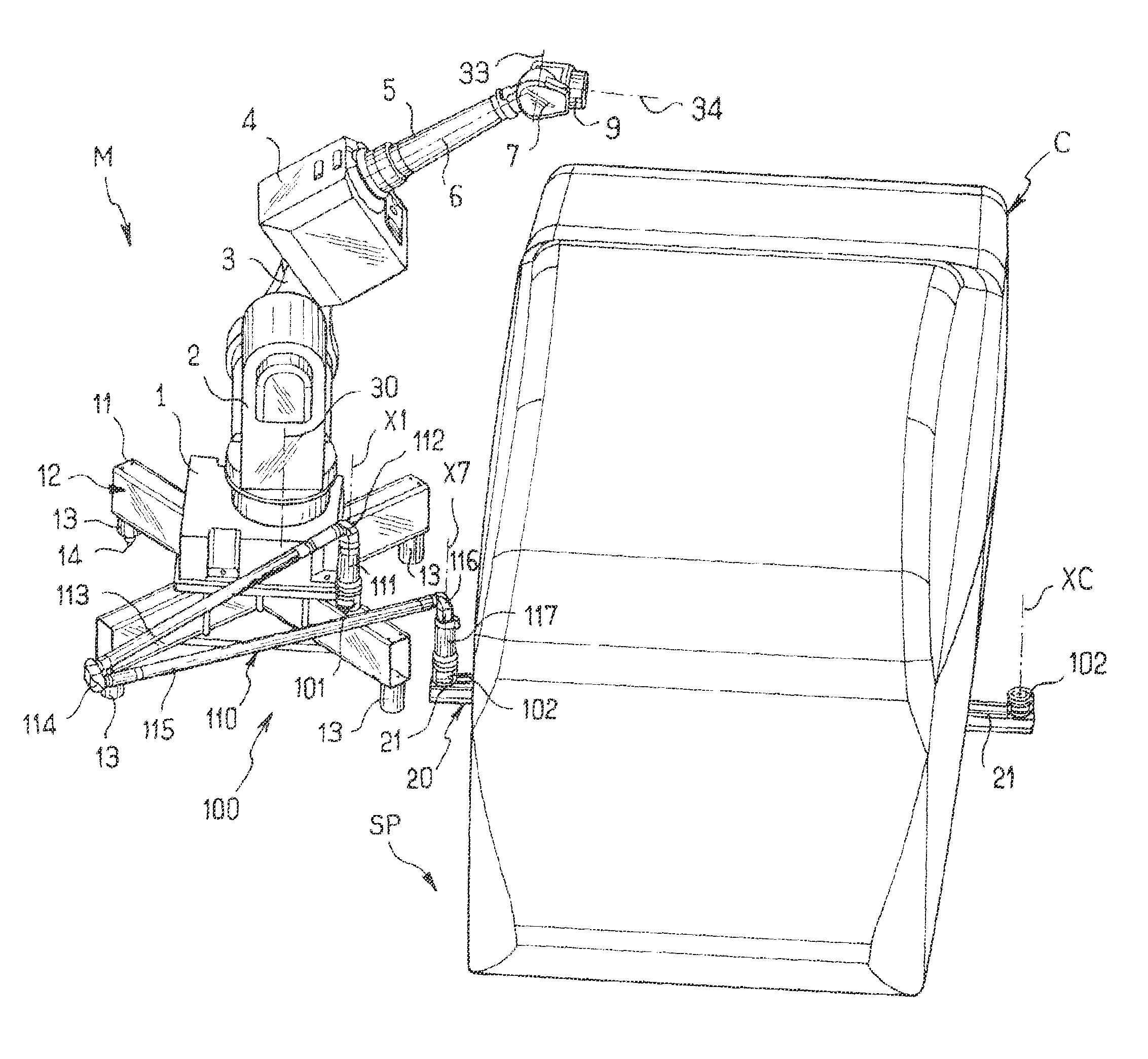
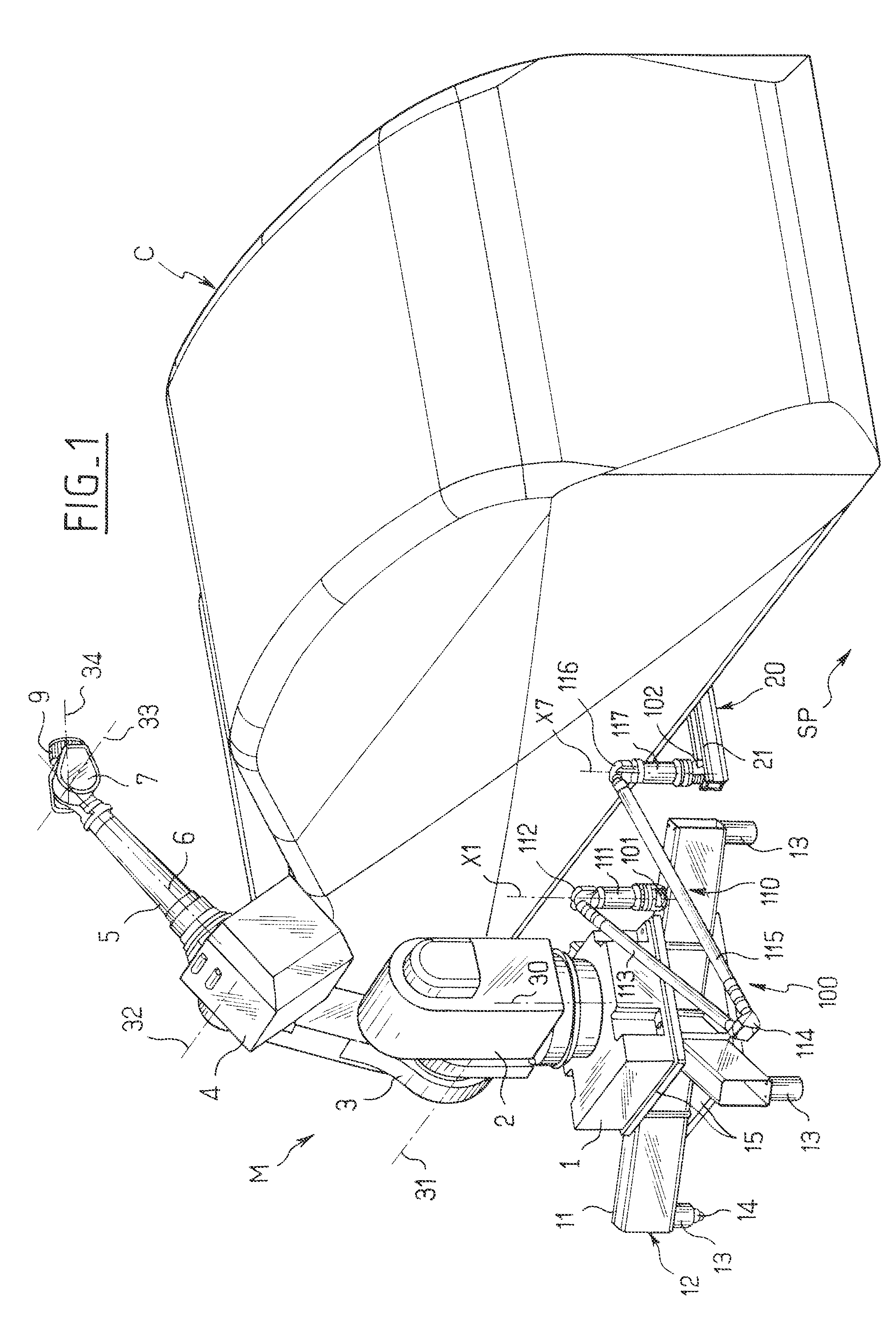
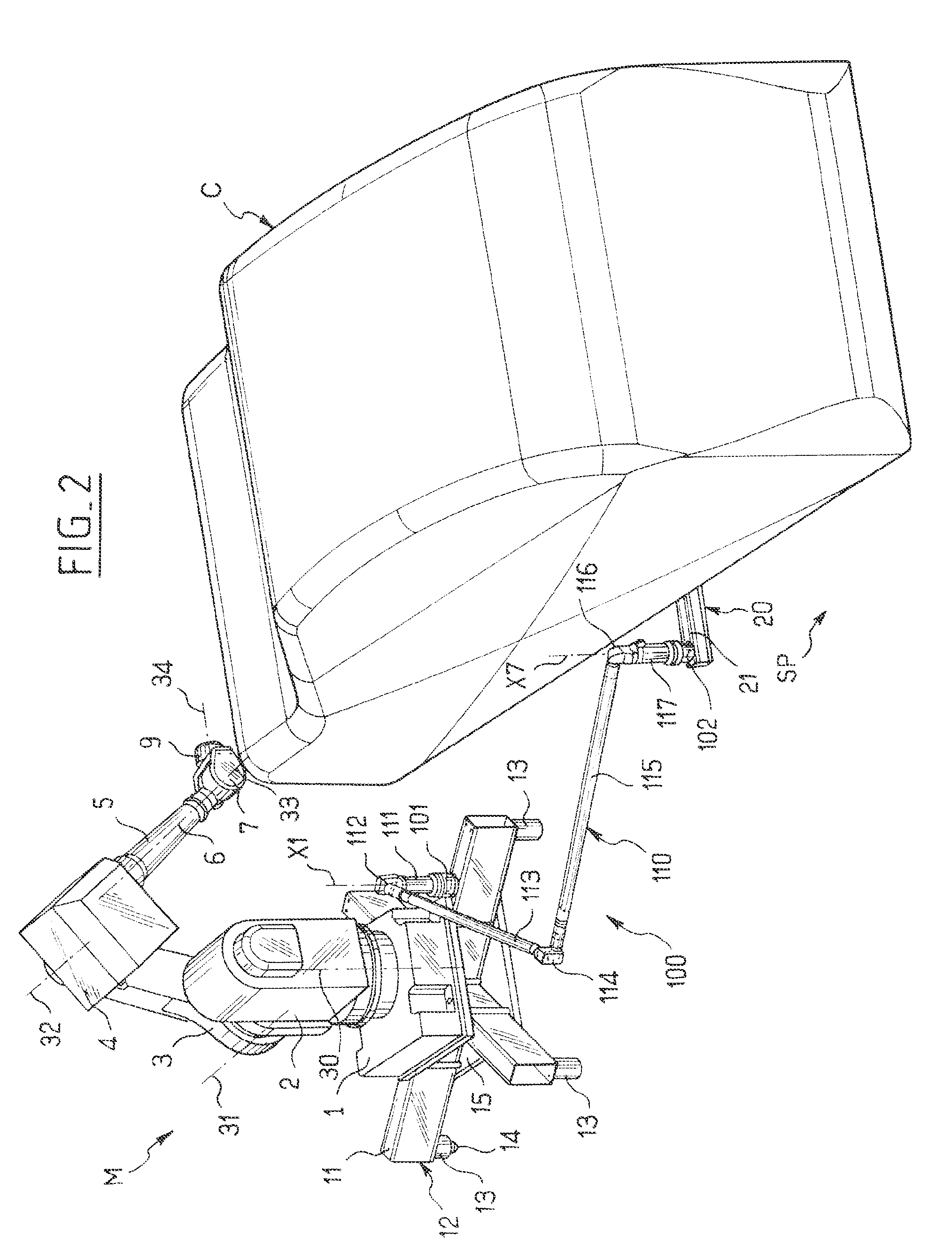
[0032]FIG. 1 shows a three-dimensional machine M having hinged arms, and specifically a milling robot for acting on a piece of motor vehicle bodywork C.

[0033]The milling machine M comprises a baseplate 1 surmounted by a turret 2 capable of turning about an axis 30 that is essentially vertical, and fitted with an arm 3 mounted to pivot about an axis 31 that is essentially horizontal. The arm 3 is in turn fitted with a functional assembly 4 mounted to pivot about an axis 32, and presenting an arm 5 with a longitudinal axis 6, said arm being terminated by a fork 7 mounted to turn about the axis 6, and also about a transverse axis 33. The end fork 7 is finally fitted with a machining tool 9, for example a rotary cutter, mounted to revolve about an axis 34.

[0034]The baseplate 1 of the machine M rests on an essentially plane support wall 11 which is associated with a machine stand 12, in this case implemented in the form of a cross-shaped assembly having end legs 13 terminated by roller e...


PUM


Abstract

The invention relates to a system for identifying the position of a machine for three-dimensional measuring or machining in a fixed frame of reference. In accordance with the invention, the system comprises:a first base for resting at an identified point on a support wall associated with the machine stand, said base being provided on its top with a bearing platform;a second base identical to the first base, for resting at an identified point on a support surface associated with the fixed frame of reference; anda multi-axis assembly having two hinged arms that are coupled together, and having two endpieces coupled to said arms, each endpiece having a main axis that coincides with the central axis of the corresponding base when said endpiece is in place, said multi-axis assembly also being fitted with integrated angle encoders measuring the respective angles of rotation about each of its axes.

Description

CROSS-REFERENCE TO RELATED APPLICATIONS[0001]Applicant hereby claims foreign priority benefits under U.S.C. § 119 from French Patent Application No. 05 10745 filed on Oct. 21, 2005, the contents of which are incorporated by reference herein.FIELD OF THE INVENTION[0002]The present invention relates to a system for identifying the position of a three-dimensional machine for measuring or machining in a fixed frame of reference.[0003]The three-dimensional machine in question may equally well be a measuring machine, in particular one making use of hinged arms, or a machine for machining, in particular a multi-axis milling machine.BACKGROUND OF THE INVENTION[0004]In the particular field of motor vehicles, there can be a need to identify various points on the bodywork of a motor vehicle that has suffered an accident or that is in the process of being assembled, in order to verify its shape by identifying predetermined points of said bodywork by means of a three-dimensional measuring device...

Claims


Application Information

Patent Timeline
Patent Type & Authority Patents(United States)
IPC IPC(8): G01B5/004G01B5/008G01B7/008
CPCG01B21/04
Inventor GRANGER, ROMAIN
Owner ROMER INC
Why Eureka
Try Eureka