Display device with illuminator connecting with relay, method for manufacturing display device, and electronic apparatus

a display device and relay technology, applied in the manufacture of electrode systems, electric discharge tubes/lamps, instruments, etc., can solve the problems of increased production costs, increased device size, and risk of irregular brightness

Active Publication Date: 2013-03-12
ELEMENT CAPITAL COMMERCIAL CO PTE LTD
View PDF6 Cites 0 Cited by
  • Summary
  • Abstract
  • Description
  • Claims
  • Application Information

AI Technical Summary

Benefits of technology

[0006]An advantage of some aspects of the invention is to provide a reflection type display device including an illuminator that does not involve an increase in the number of FPC required. In addition, the invention provides, as an advantage of some aspects thereof, a method for manufacturing the display device, and an electronic apparatus.
[0008]In the structure of a display device according to the first aspect of the invention, it is preferable that the illumination medium should further include an illumination substrate on or over which the light-emitting element and the connection portion are formed; and the illumination substrate should be interposed between the connection portion and the relay wiring. In the structure of a display device according to the first aspect of the invention, it is preferable that the illumination medium should further include an illumination substrate on or over which the light-emitting element and the connection portion are formed; the display medium should further include a display substrate on or over which the terminal, the relay wiring, and the electro-optical element are formed; the connection portion should lie on or over a display-medium-side surface of the illumination substrate, which is a surface closer to the display medium; the relay wiring should lie on or over an illumination-medium-side surface of the display substrate, which is a surface closer to the illumination medium; and the connection portion and the relay wiring should face each other with the conductor being sandwiched between the connection portion and the relay wiring. In the latter of the two preferred configurations described above, it is not necessary for the conductor to, for example, extend across and outside an edge face of the illumination substrate circuitously. Such a preferred configuration is advantageous in that the length of a connection path between the relay wiring and the connection portion can be shortened.
[0009]In the structure of a display device according to the first aspect of the invention, it is preferable that the number of the conductor should be more than one; the illumination medium should further include an illumination substrate on or over which the light-emitting element and the connection portion are formed; the illumination substrate should have a plurality of edges; the connection portion should include a first connection portion and a second connection portion, the second connection portion being not the same as the first connection portion; the first connection portion should be electrically connected to the relay wiring via one of the conductors that extends across one of the edges of the illumination substrate; and the second connection portion should be electrically connected to the relay wiring via another one of the conductors that extends across another one of the edges of the illumination substrate. Generally, there is a risk of irregular brightness due to a voltage drop in a case where an electrode wire is routed as long wiring in the structure of an illumination medium. In this respect, a display device having such a preferred structure is advantageous in that it is possible to suppress a voltage drop and to reduce uneven brightness even when an electrode wire that is electrically connected to both the first connection portion and the second connection portion is routed as long wiring.
[0010]In the structure of a display device according to the first aspect of the invention, it is preferable that the number of the electro-optical element should be more than one; the display medium should further include a common electrode, which is an electrode common to the plurality of electro-optical elements; and the relay wiring should be electrically connected to the common electrode and be used also for supplying power to the electro-optical elements. Or, a display device according to the first aspect of the invention may be preferably configured as follows; the display medium further includes a control circuit that controls electric energy supplied to the electro-optical element; and the relay wiring is electrically connected to the control circuit and is used also for supplying power to the control circuit. In both of the two preferred configurations described above, at least one power line is used for the purpose of supplying power to the illumination medium and supplying power to the display medium, that is, doubles as an illumination power line and a display power line. In addition, at least one power supply is used as both a power supply for the illumination medium and a power supply for the display medium. Such a configuration has an advantage in terms of simple circuitry.

Problems solved by technology

The increased number of FPCs that need to be mounted causes an increase in production cost and an increase in the size of the device.
Generally, there is a risk of irregular brightness due to a voltage drop in a case where an electrode wire is routed as long wiring in the structure of an illumination medium.

Method used


Image

  • Display device with illuminator connecting with relay, method for manufacturing display device, and electronic apparatus
  • Display device with illuminator connecting with relay, method for manufacturing display device, and electronic apparatus
  • Display device with illuminator connecting with relay, method for manufacturing display device, and electronic apparatus

Examples


first embodiment

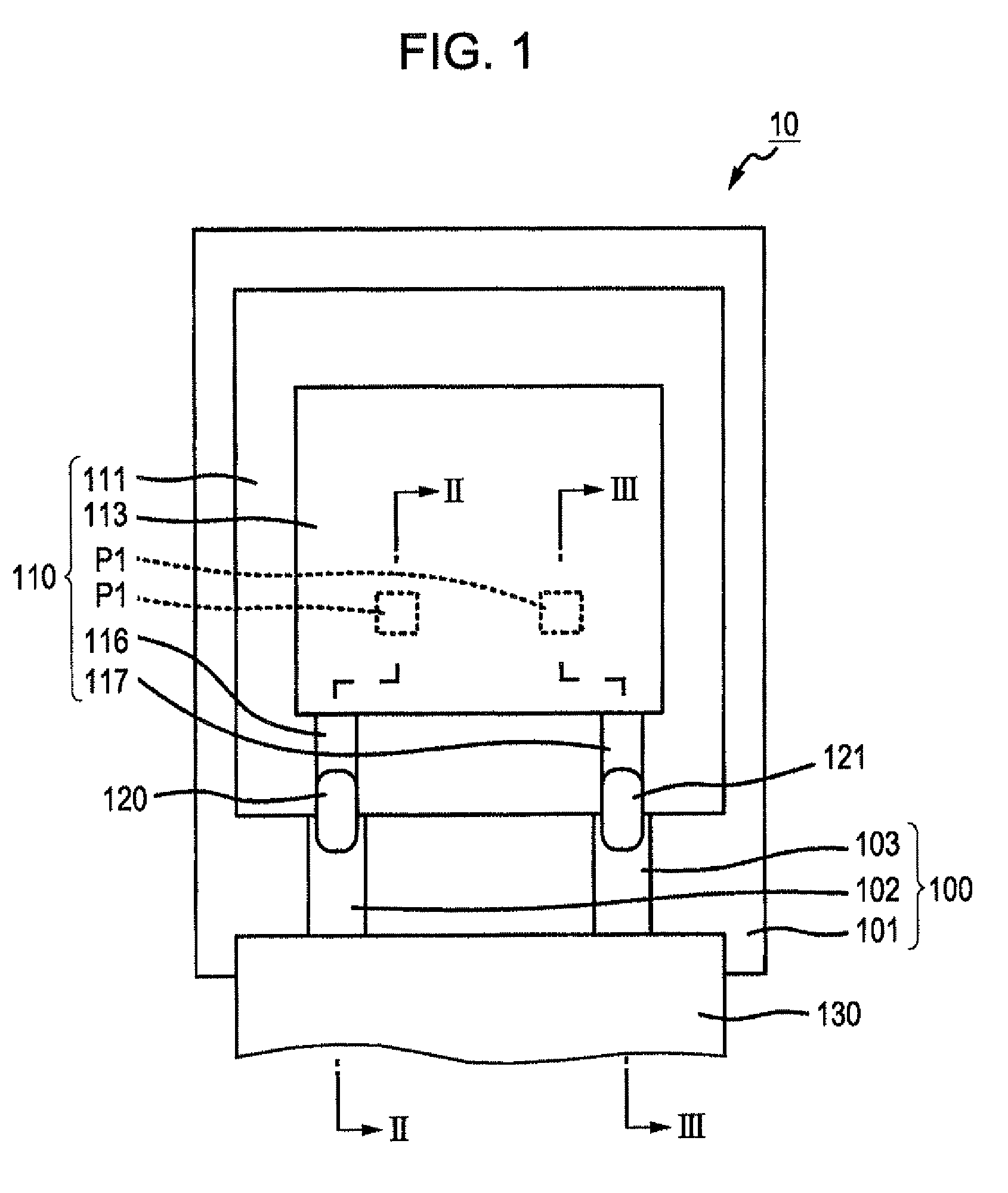
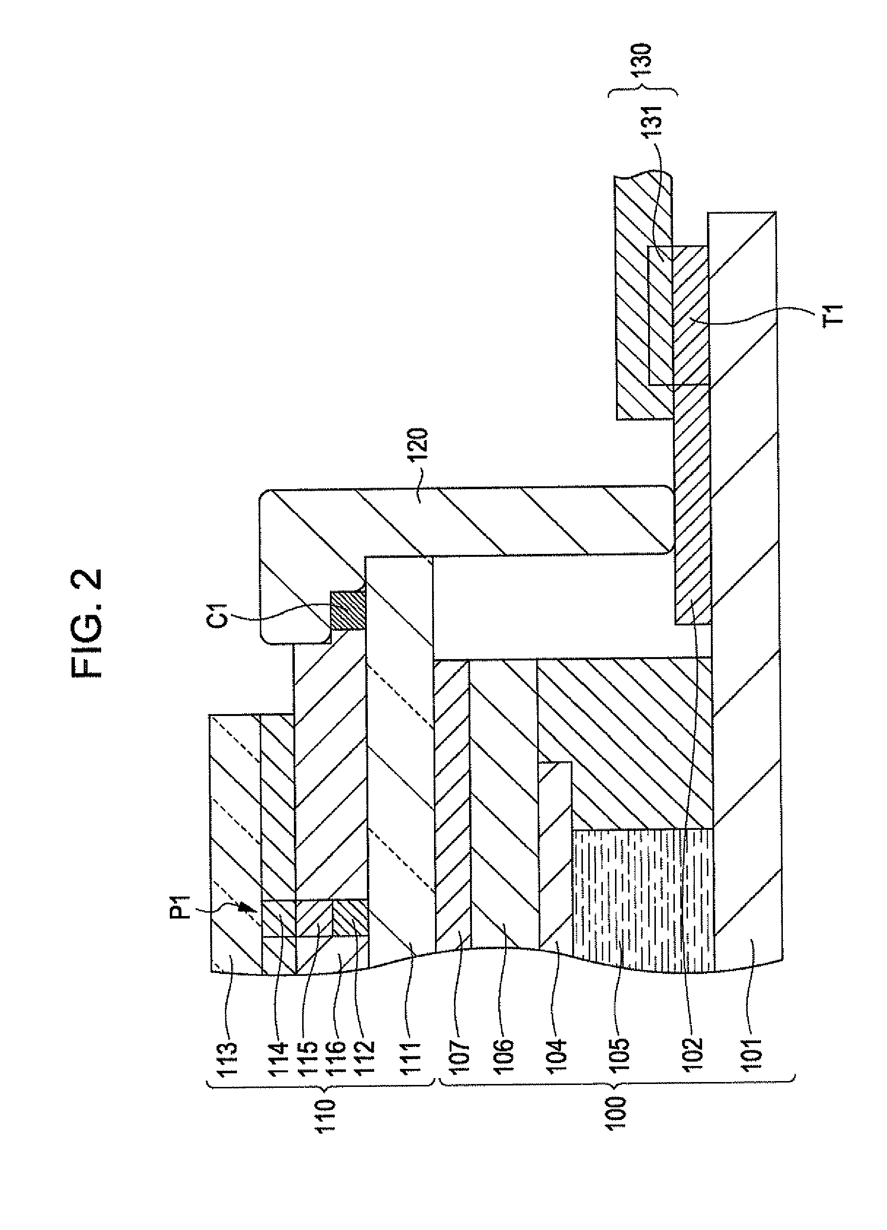
[0035]FIG. 1 is a plan view that schematically illustrates an example of the configuration of a display device 10 according to a first embodiment of the invention. FIG. 2 is a sectional view taken along the line II-II of FIG. 1. FIG. 3 is a sectional view taken along the line III-III of FIG. 1. As illustrated in these drawings, the display device 10 is provided with a reflection type display medium 100, an illumination medium (i.e., illuminator) 110, conductive bodies (i.e., electric conductors) 120 and 121, and a flexible printed circuit (FPC) 130. The display medium 100 utilizes reflected light for displaying an image. The illuminator 110 irradiates light to the display medium 100. Each of the electric conductors 120 and 121 provides connection like a bridge between the display medium 100 and the illuminator 110. The FPC 130 is connected to the display medium 100.

[0036]The display medium 100 is a reflection type liquid crystal display device. The display medium 100 includes a disp...

second embodiment

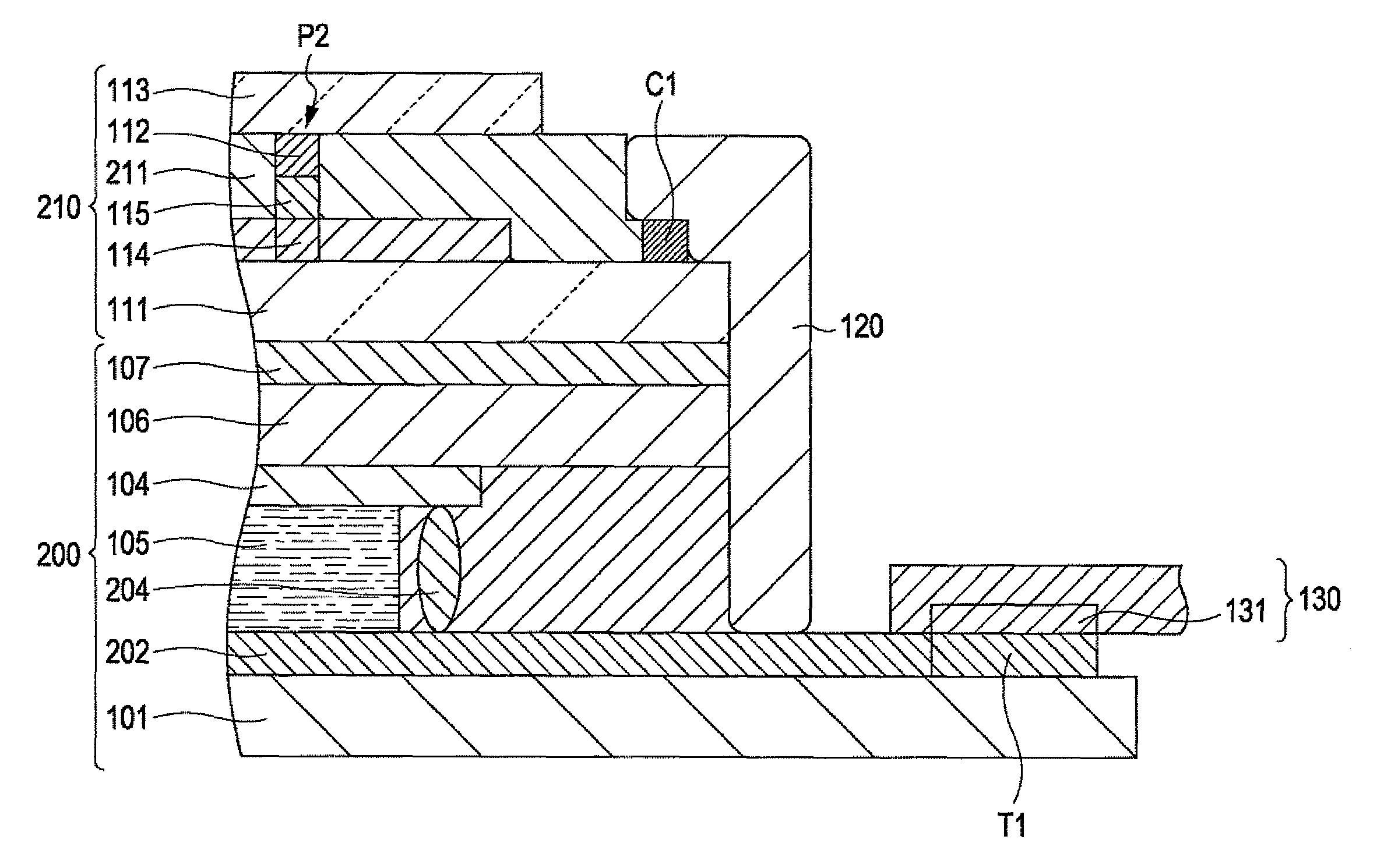
[0050]FIG. 7 is a plan view that schematically illustrates an example of the configuration of a display device 20 according to a second embodiment of the invention. FIG. 8 is a sectional view taken along the line VIII-VIII of FIG. 7. FIG. 9 is a sectional view taken along the line IX-IX of FIG. 7. As illustrated in these drawings, the display device 20 is provided with a reflection type display medium 200, an illuminator 210, the electric conductors 120 and 121, and the FPC 130. The display medium 200 utilizes reflected light for displaying an image. The illuminator 210 irradiates light to the display medium 200. Each of the electric conductors 120 and 121 provides connection like a bridge between the display medium 200 and the illuminator 210. The FPC 130 is connected to the display medium 200.

[0051]The configuration of the display medium 200 is different from that of the display medium 100 in the following points; firstly, the display medium 200 is not provided with the relay wire...

third embodiment

[0055]FIG. 10 is a plan view that schematically illustrates an example of the configuration of a display device 30 according to a third embodiment of the invention, FIG. 11 is a sectional view taken along the line XI-XI of FIG. 10. FIG. 12 is a sectional view taken along the line XII-XII of FIG. 10. As illustrated in these drawings, the display device 30 is provided with the display medium 200, the illuminator 210, electric conductors 320 and 321, and the FPC 130. The electric conductor 320 is made of silver, which is the same material as that of the electric conductor 120. The electric conductor 320 provides electric connection between the relay wire 202 and the connection portion C1. The electric conductor 321 is also made of silver, the same material as that of the electric conductor 121. The electric conductor 321 provides electric connection between the relay wire 103 and the connection portion C2. Having the above structure, the display device 30 offers the same advantage as t...


PUM

PropertyMeasurementUnit
voltageaaaaaaaaaa
voltageaaaaaaaaaa
voltageaaaaaaaaaa

Abstract

A display device includes an illumination medium, a display medium, and a conductor. The illumination medium includes a light-emitting element and a connection portion. The light-emitting element includes a first electrode and a second electrode and emits light with the use of power supplied between the first electrode and the second electrode. The connection portion is electrically connected to at least one of the first electrode and the second electrode. The display medium includes a terminal, relay wiring, and an electro-optical element. The relay wiring is electrically connected to the terminal. The electro-optical element controls light that is irradiated by and comes from the illumination medium according to electric energy supplied to the electro-optical element. The conductor electrically connects the relay wiring and the connection portion.

Description

BACKGROUND[0001]1. Technical Field[0002]The present invention relates to a reflection type display device including an illuminator, a method for manufacturing the display device, and an electronic apparatus.[0003]2. Related Art[0004]A reflection type display device with an illumination function that includes a reflective display medium (e.g., reflection type liquid crystal display device) and an illumination medium (e.g., illumination device) is disclosed in JP-A-2006-323304 (refer to FIG. 2). The illumination medium irradiates light to the display medium. In JP-A-2008-218175, an illumination medium (e.g., illumination device) that is a component of a reflection type display device having an illumination function is disclosed (refer to FIG. 10). It is described in these patent documents that organic electroluminescent (EL) elements are used as a light source for an illumination medium. Since an illumination medium irradiates light to a reflective display medium, a reflection type di...

Claims


Application Information

Patent Timeline
Patent Type & Authority Patents(United States)
IPC IPC(8): G02F1/1335G02F1/1345
CPCG02F1/133603G02F2001/133612G02F1/133612
Inventor KUBOTA, TAKEHIKO
Owner ELEMENT CAPITAL COMMERCIAL CO PTE LTD
Why Eureka
Try Eureka