
Air intake arrangement for an aircraft

a technology for air intake and aircraft, applied in the direction of machines/engines, transportation and packaging, combustion-air/fuel-air treatment, etc., to achieve the effect of limiting vibration

Active Publication Date: 2013-03-19
AIRBUS OPERATIONS (SAS)
View PDF9 Cites 3 Cited by
  • Summary
  • Abstract
  • Description
  • Claims
  • Application Information

AI Technical Summary

Benefits of technology

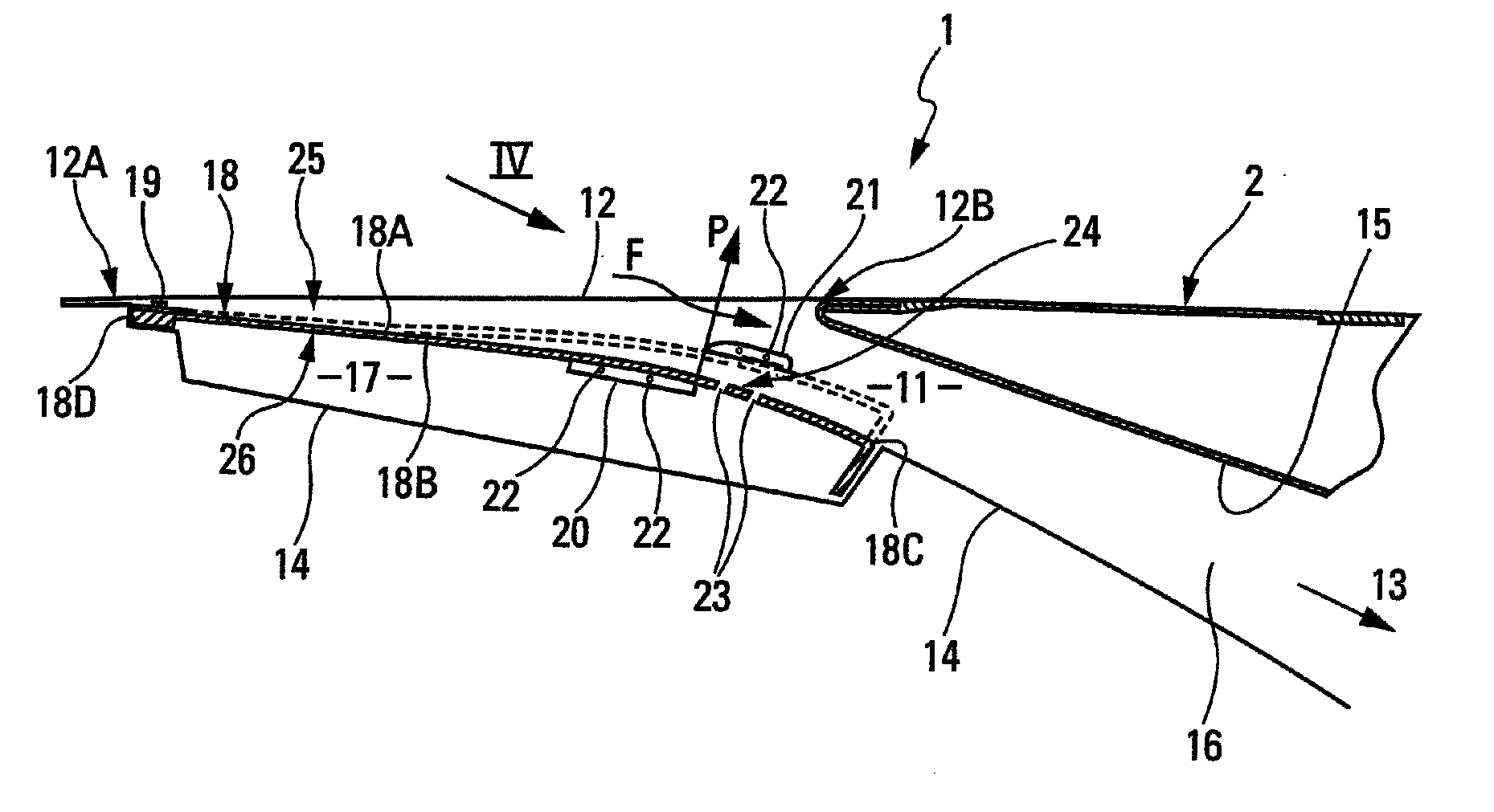
The invention is about a mobile plate in an air intake arrangement of an aircraft that can adjust the pressure in the extended area of the internal side of the plate to that of the limited downstream area with high pressure, resulting in the plate being moved and partially plugging the cross-section of the channel. This is especially important during the takeoff phase, where the high pressure of the upstream area on the external side of the plate can help to maintain it in a position that maximizes the cross-section of the channel. The air intake arrangement is also designed to adapt the amount of air taken by the air intake for each flight phase, minimizing the penalty of the aircraft performance due to ventilation. The air passage channel can also have low and high abutments to stabilize and limit vibrations of the plate in its maximum and minimum opening positions of the channel.

Problems solved by technology

On the contrary, during a takeoff, waiting or ground taxiing phase, the low pressure at the level of the limited downstream area (and thus of the extended area) does not allow said plate to be moved.

Method used


Image

  • Air intake arrangement for an aircraft
  • Air intake arrangement for an aircraft
  • Air intake arrangement for an aircraft

Examples


Embodiment Construction

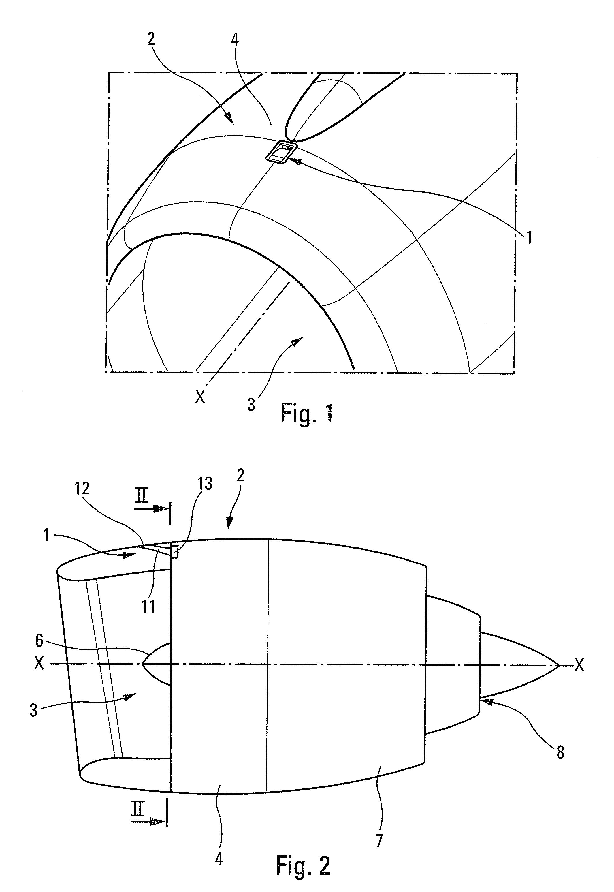
[0033]The air intake arrangement 1 according to this invention and shown in FIGS. 1 and 2 is provided within the pod 2 of an engine on-board an aircraft.

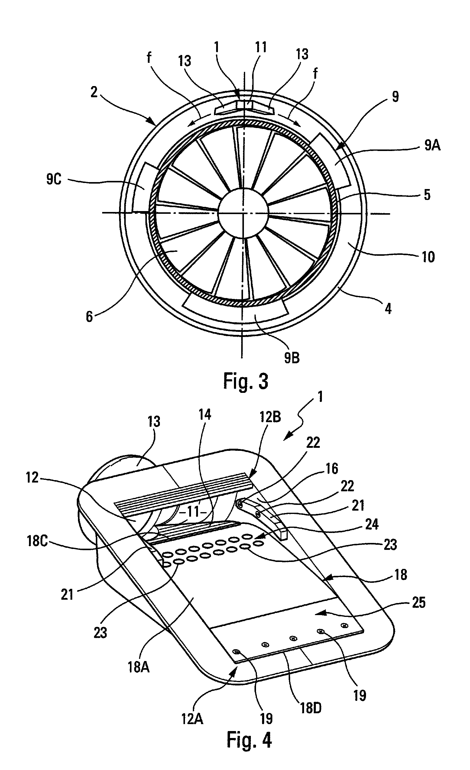
[0034]As schematically shown in FIGS. 1 to 3, the pod usually comprises an air intake front part 3 intended for supplying the engine with air, an intermediary part 4, surrounding the external case 5 of the blower 6 and the compressors of the engine, and a rear part 7, surrounding the combustion chamber and the turbine, from which the external case of the nozzle 8 and the cone thereof emerge.

[0035]Different devices or mechanical and / or electrical equipment materials 9 are arranged on the external case 5 of the blower 6 and of the compressors, i.e., in the annular enclosed area 10 between the pod 2 and the external case 5 of the engine. FIG. 3 symbolically shows some of the devices 9 arranged in such an area 10, namely the fadec 9A, the accessory gearbox 9B and the engine oil tank 9C.

[0036]Air refreshment in such an enclosed area 10, ...


PUM


Abstract

An air intake arrangement includes a mobile plate controlled by at least one fluid communication passage or opening extending between the outer and inner surfaces of the mobile plate. The fluid communication passage or opening is located at least in the vicinity of a limited downstream area of the outer surface, is at a high pressure when the aircraft flies at cruising speed, and is capable of transmitting the high pressure to an extended area of the inner surface. The air flowing through the air intake arrangement may be used to refresh an enclosed area with electrical or mechanical equipment.

Description

[0001]This application claims priority, under Section 371 and / or as a continuation under Section 120, to PCT Application No. PCT / FR2009 / 001179, filed on Oct. 5, 2009, which claims priority to French Application No. 0805525, filed on Oct. 7, 2008.TECHNICAL FIELD[0002]The present invention relates to an air intake arrangement for an aircraft comprising an air passage channel with an air intake hole.BACKGROUND[0003]It is known that such air intake arrangements are widely used in the aeronautic field with air refreshing purposes in an enclosed area containing heat sensitive materials and / or dangerous surroundings, of the flammable or explosive type, for which it is required to provide a continuous ventilation of the area so as to avoid any risk of malfunction of the materials or of surrounding incident.[0004]This is more specifically the case of numerous mechanical and / or electrical devices provided in the annular enclosed area between the pod and the external case of the blower and com...

Claims


Application Information

Patent Timeline
Patent Type & Authority Patents(United States)
IPC IPC(8): F02C7/04
CPCB64D33/08B64D2241/00Y10T137/0536
Inventor PORTE, ALAINCHANCERELLE, EMERICALVAREZ, FRANCKPRAT, DAMIEN
Owner AIRBUS OPERATIONS (SAS)
Learn More