Air intake arrangement for a vehicle, in particular an aircraft

Active Publication Date: 2016-08-23
AIRBUS OPERATIONS (SAS)
View PDF29 Cites 1 Cited by
  • Summary
  • Abstract
  • Description
  • Claims
  • Application Information

AI Technical Summary

Benefits of technology

[0008]It is an object of the present invention to provide a solution to these disadvantages and the invention relates to an air intake arrangement the design of which allows optimal ventilation of a confined zone like that described hereinabov

Problems solved by technology

However, because the amount of external air entering the air channel of preset cross section is dependent in particular on parameters associated with the speed of the aircraft and the altitude thereof, it is difficult for the devices that need to be cooled and the vapor that needs to be expelled to be ventilated optimally.
The problem is that although the external air entering the channel of preset cross section of the arrangement via the air intake orifice upstream and leaving downstream of this channel is sufficient in quantity to ventilate the devices correctly when the aircraft is rolling along the ground, in a take-off phase or on standby, and therefore at low speed, when the aircraft is in c

Method used


Image

  • Air intake arrangement for a vehicle, in particular an aircraft
  • Air intake arrangement for a vehicle, in particular an aircraft
  • Air intake arrangement for a vehicle, in particular an aircraft

Examples


Embodiment Construction

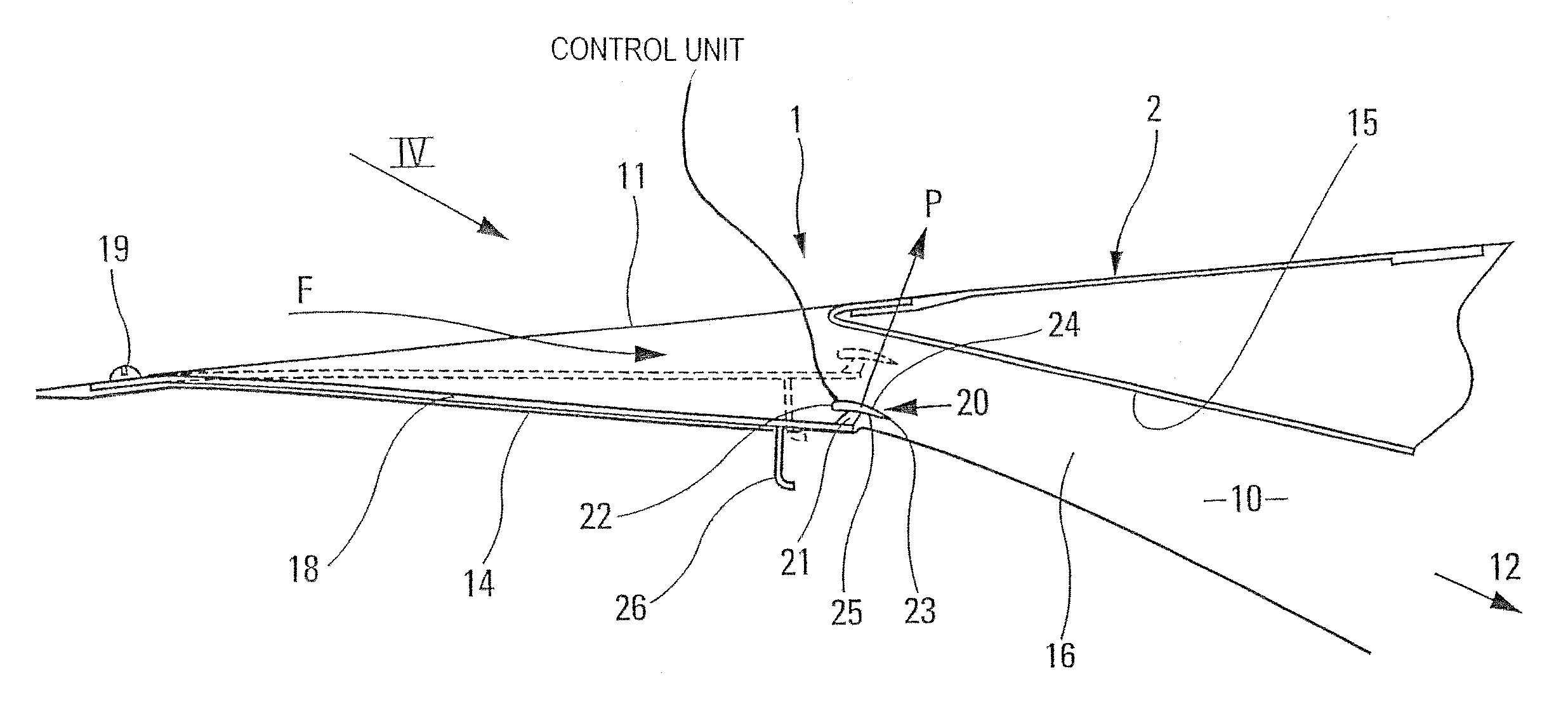
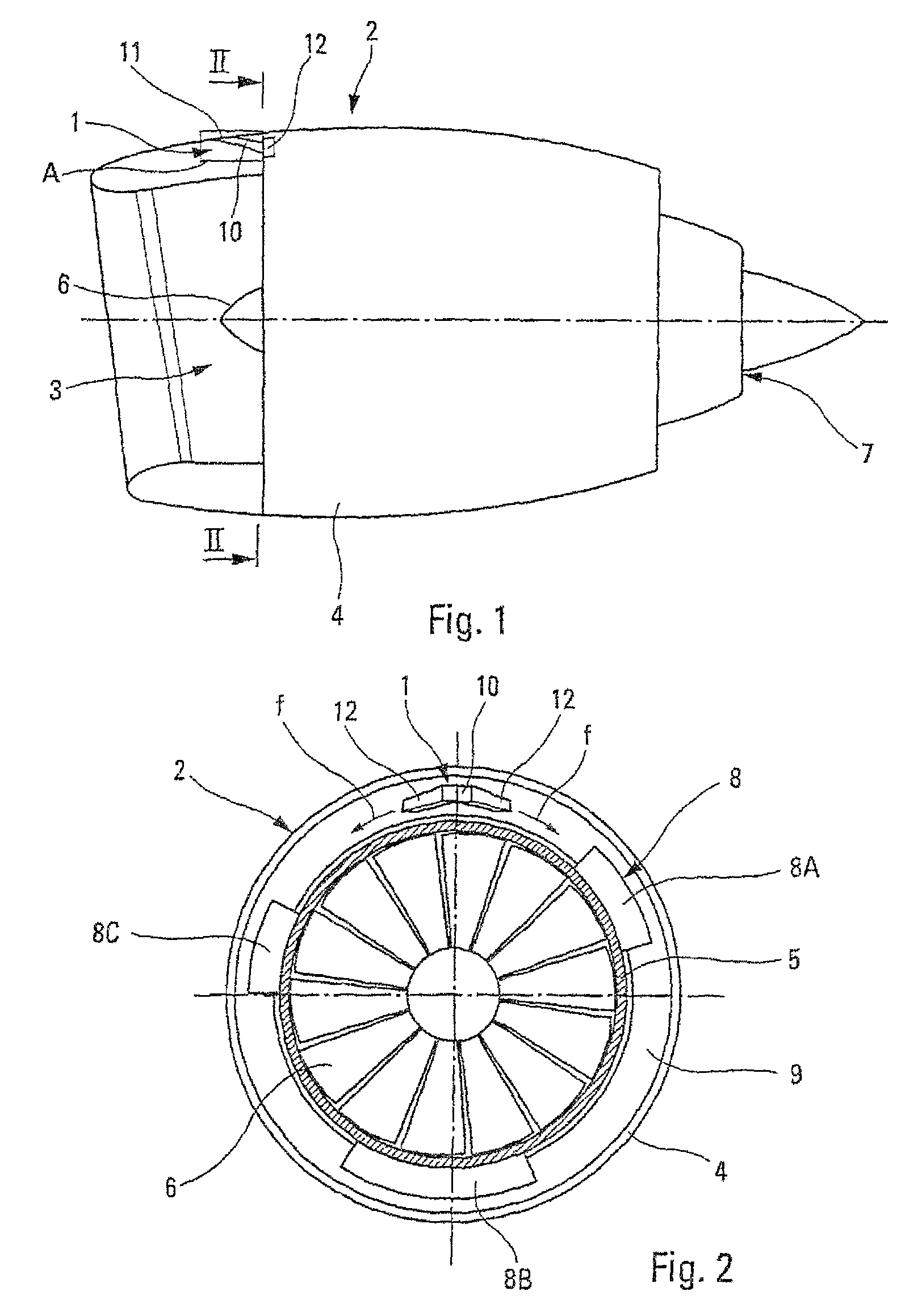
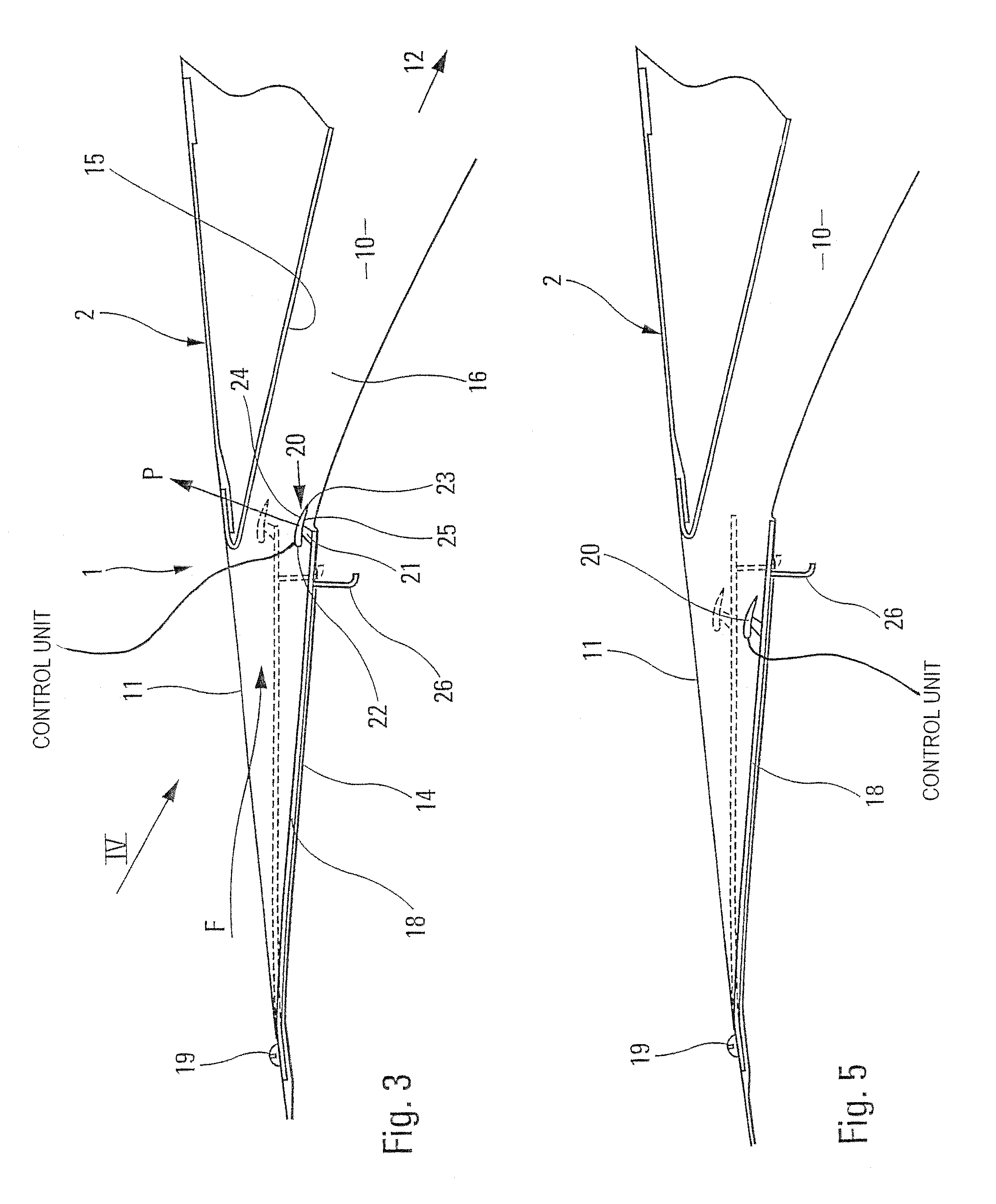
[0029]The air intake arrangement 1 according to the invention and symbolized by a rectangle A in FIG. 1 is provided in a nacelle 2 of an engine mounted on an airplane (not depicted). As shown schematically by FIGS. 1 and 2, the nacelle 2 comprises, in the usual way, an air intake front part 3 for supplying the engine with air, an intermediate part 4 surrounding the external casing 5 of the fan 6, the engine compressors and the combustion chamber and turbine, from which there emerges the external casing of the jet pipe 7 and its cone.

[0030]Various mechanical and / or electrical devices or items of equipment 8 are attached to the external casing 5 of the fan and of the compressors, that is to say in the confined annular zone 9 between the nacelle 2 and the external casing 5 of the engine. FIG. 2 symbolically depicts some of the devices 8 that can be found in this zone 9, namely the fadec 8A, the accessory relay box 8B and the engine oil reservoir 8C.

[0031]The air in this confined zone 9...


PUM


Abstract

Disclosed is an air intake arrangement for an aircraft. The arrangement includes an air intake orifice, which is configured to bleed off a flow of external air, pass the external air through at least one air passage channel and ventilate a confined zone of the aircraft. An aerodynamically controlled shut-off means, comprised of a controllable mobile element and control means, is configured to regulate flow of the external air through the air passage channel to vary a cross section of the air passage channel relative to aircraft speed. The control means are arranged in the air passage channel and include an aerodynamic surface configured to apply a lift force to the control means to vary the cross section of the air passage channel as the flow of external air passes through the channel and toward the confined zone.

Description

FIELD OF THE INVENTION[0001]The present invention relates to an air intake arrangement for a vehicle, particularly for an aircraft, comprising an air passage channel with an air intake orifice.BACKGROUND OF THE INVENTION[0002]It is known that such air intake arrangements are in widespread use in the field of aeronautics, particularly, although not exclusively, for the purposes of renewing the air in a confined zone containing temperature-sensitive equipment and / or hazardous surroundings, of the flammable or explosive type, which require the zone to be continuously ventilated in order to avoid any risk of equipment malfunction or surrounding incident.[0003]This is the case in particular with numerous mechanical and / or electrical devices provided in the confined annular zone between the nacelle and the outer fan case and compressor casing of an aircraft turbojet engine. These devices, such as the fades (full authority digital engine control), the accessory relay box (gearbox), the eng...

Claims


Application Information

Patent Timeline
IPC IPC(8): B64D33/02B64D33/08
CPCB64D33/02B64D33/08B64D2033/0286
Inventor ALVAREZ, FRANCKCHANCERELLE, EMERICPORTE, ALAINPRAT, DAMIEN
Owner AIRBUS OPERATIONS (SAS)
Why Eureka
Try Eureka