Device for providing rotational torque and method of use

a technology of rotational torque and rotating shaft, which is applied in the direction of dynamo-electric machines, electrical apparatus, dc commutators, etc., can solve problems such as rotational stall, and achieve the effect of reducing separation forces and reducing energy loss

Inactive Publication Date: 2013-03-19
WOJTOWICZ CHRIS
View PDF21 Cites 22 Cited by
  • Summary
  • Abstract
  • Description
  • Claims
  • Application Information

AI Technical Summary

Benefits of technology

[0003]In view of the above described problem, an object of the present invention is to provide a means for reducing the separation forces in a permanent magnetic gate thereby reducing the energy loss.

Problems solved by technology

However, this arrangement runs into a problem when trying to rotate past the last set of stator magnets which are closest to the poles of the rotor magnet.
The effect known as cogging will tend to cause the rotor magnet to hold onto the stator magnet with the highest amount of attraction, thereby causing the rotor to stall.
Electro-magnets, however require an external power source, which has been a seemingly inescapable feature of the common permanent magnet motor.

Method used


Image

  • Device for providing rotational torque and method of use
  • Device for providing rotational torque and method of use
  • Device for providing rotational torque and method of use

Examples


Embodiment Construction

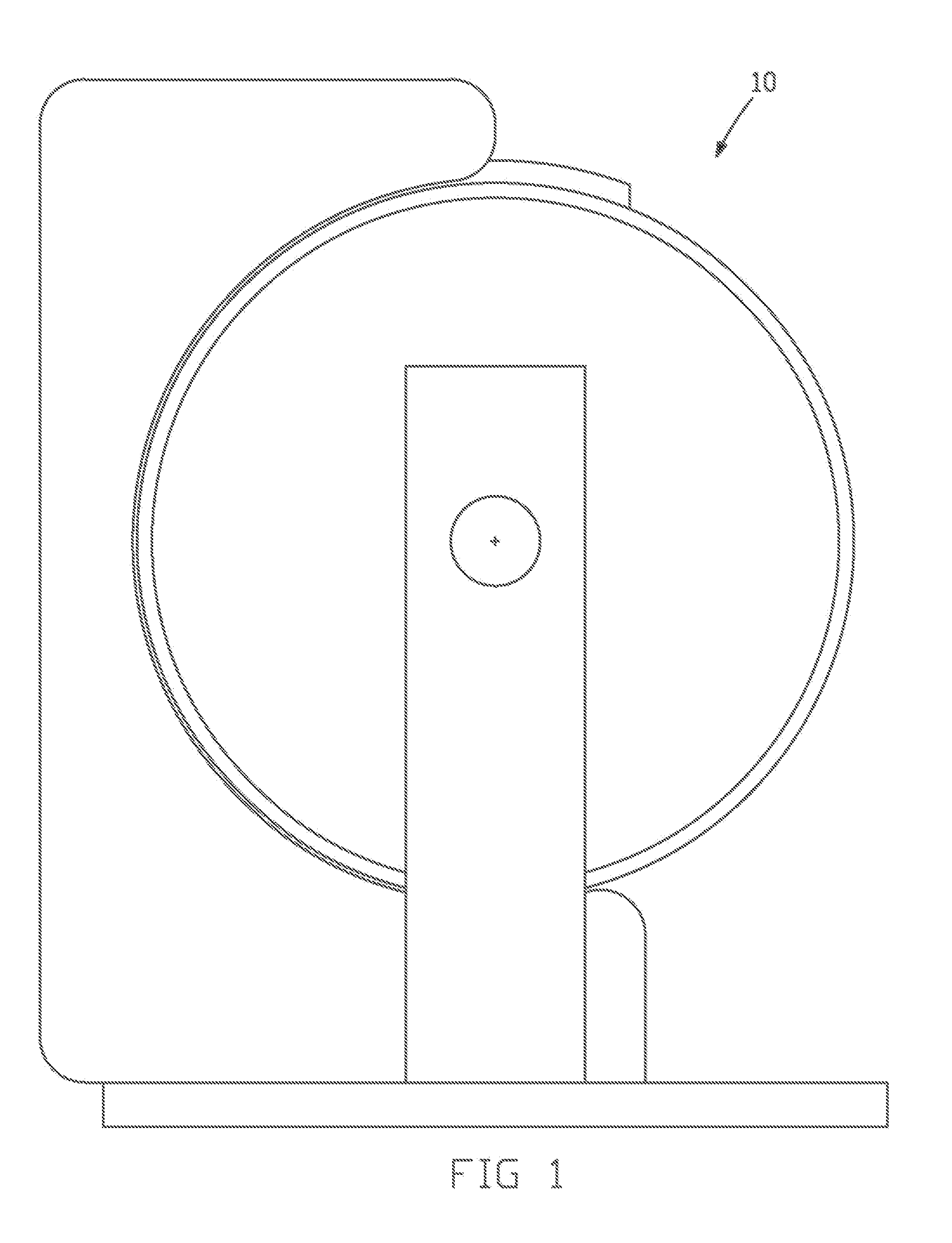
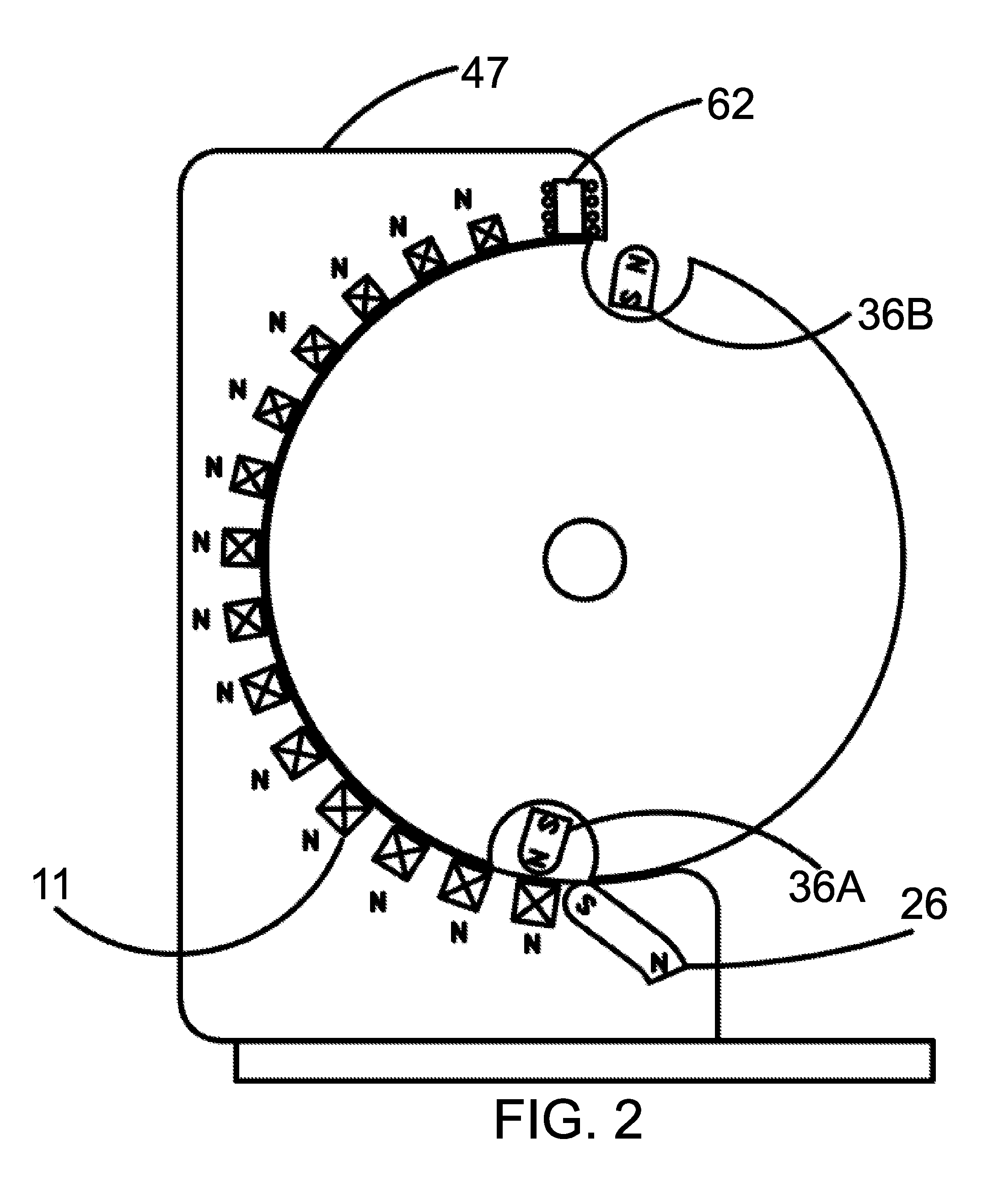
[0020]With reference to FIGS. 1-5, an embodiment of a permanent magnet motor 10 and method of use that provide a magnetic gate that allows continued motion of a rotor relative to a stator without an external power source and with low cogging will be described. Although a permanent magnet motor is shown and described herein as an exemplary device for providing rotational torque, in alternative embodiments, the aspects of the present invention shown and described herein are applied to other types of devices for providing rotational torque. Permanent magnet motor 10 is an axial motor including a drive shaft 8 that penetrates a vertical support 4A, a bearing 6A, a rotor cam 18, a support plate 46, a rotor 48, a cam support 50, a stator cam plate 9, a bearing 6B, and a vertical support 4B. The vertical supports 4A and 4B are fixed to and supported by a base 2, with a gap left relative to the drive shaft 8. The stator cam plate 9, stator support 50, rotor 48, rotor support plate 46, and b...


PUM


Abstract

A device for providing rotational torque includes a stator with a permanent magnet rotatably mounted contained within, a rotor arranged on one side of the stator, a pair of permanent magnets rotatably mounted on oppositely spacing sides of the rotor, which stator and rotors are arranged with gaps left therebetween in an axial direction of the driveshaft, the rotor being mounted to the driveshaft. For further acceleration of the rotor, there are mounted several permanent magnets in the stator housing, arranged in a circumferential arrangement relative to the rotor. These acceleration magnets are arranged such that the size increases with each acceleration magnet approaching the stator magnet.

Description

FIELD OF THE INVENTION[0001]The present invention is, in general, in the field of devices for providing rotational torque, and, in particular, in the field of permanent magnet motors.BACKGROUND OF THE INVENTION[0002]In known permanent magnet motors, the attractive forces of the stator magnets will cause the rotor to turn until the highest degree of attraction is obtained. However, this arrangement runs into a problem when trying to rotate past the last set of stator magnets which are closest to the poles of the rotor magnet. The effect known as cogging will tend to cause the rotor magnet to hold onto the stator magnet with the highest amount of attraction, thereby causing the rotor to stall. Electro-magnets are employed in the vast majority of permanent magnet motors to keep the rotor moving past the stator magnets. Electro-magnets, however require an external power source, which has been a seemingly inescapable feature of the common permanent magnet motor.SUMMARY OF THE INVENTION[0...

Claims


Application Information

Patent Timeline
Patent Type & Authority Patents(United States)
IPC IPC(8): H02K37/00
CPCH02K53/00
Inventor WOJTOWICZ, CHRIS
Owner WOJTOWICZ CHRIS
Why Eureka
Try Eureka