LED spotlight including elliptical and parabolic reflectors

a technology of parabolic reflectors and lampshade, which is applied in the field of led spotlights including elliptical and parabolic reflectors, can solve the problems that the lamps used as alternatives to parabolic aluminized reflectors (par) lamps cannot match the photometric performance for a given frontal area

Active Publication Date: 2013-03-26
HONEYWELL INT INC
View PDF18 Cites 29 Cited by
  • Summary
  • Abstract
  • Description
  • Claims
  • Application Information

AI Technical Summary

Benefits of technology

[0002]Instead of a simple forward facing planar array that might typically be used for a PAR lamp replacement, the present invention uses depth of the package to increase the total peak intensity. One or more layers of LEDs shine into an array of elliptical reflectors. Each elliptical reflector has an LED at one focal point and shares the second focal point with a larger parabolic reflector that collimates the light. The resulting system has a hole in the center of the parabolic reflector where additional layers of LEDs, with or without collimation optics, are placed to further increase the intensity of the system. This configuration allows the distribution to be adjusted for the application (wavelength, peak intensity and beam spread) by changing the number or type of LED, the focal lengths of the ellipses, the parabola and the collimation optics.

Problems solved by technology

Many LED lamps used as alternatives to Parabolic Aluminized Reflector (PAR) lamps cannot match the photometric performance for a given frontal area compared to the conventional lamps they would replace, particularly for applications that require very high peak intensities such as a PAR64 aircraft landing light or an entertainment stage light.

Method used


Image

  • LED spotlight including elliptical and parabolic reflectors
  • LED spotlight including elliptical and parabolic reflectors
  • LED spotlight including elliptical and parabolic reflectors

Examples


Embodiment Construction

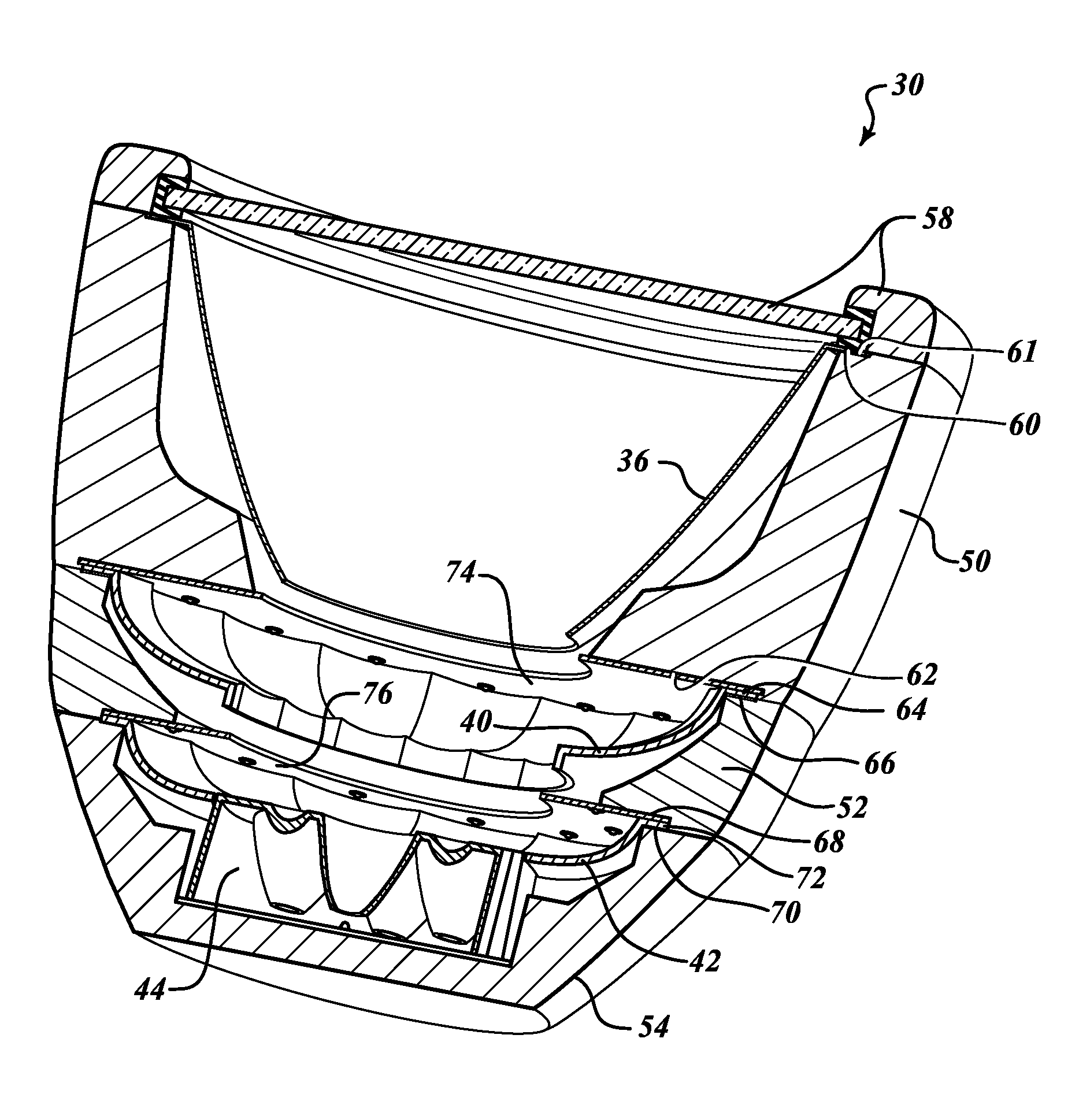
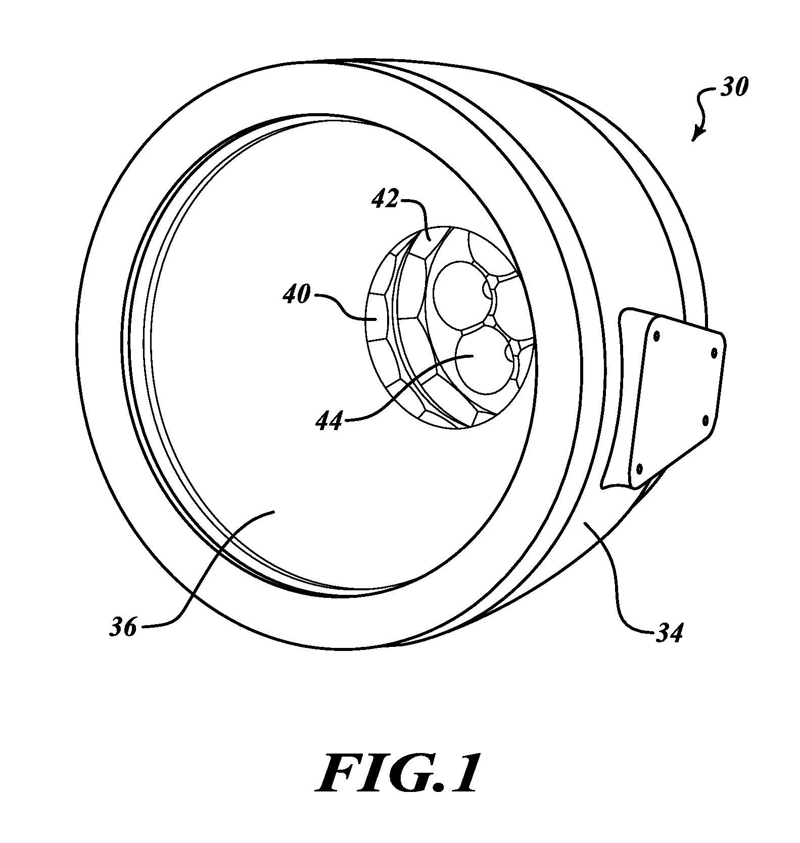
[0012]FIG. 1 illustrates a perspective view of a light assembly 30 formed in accordance with an embodiment of the present invention. The light assembly 30 is capable of producing a greater intensity of light than that produced by conventional light emitting diode (LED) light assemblies of comparable anterior dimension. The light assembly 30 includes a housing 34 which is capped at one end by a lens 58. Inside the housing 34 are a large parabolic reflector 36 and a plurality of layers 40, 42, 44 of LEDs with elliptical reflectors and / or parabolic reflectors. Light produced by the LEDs either passes directly through ends of the large parabolic reflector 36 or the large parabolic reflector 36 collimates light received from the elliptical reflectors.

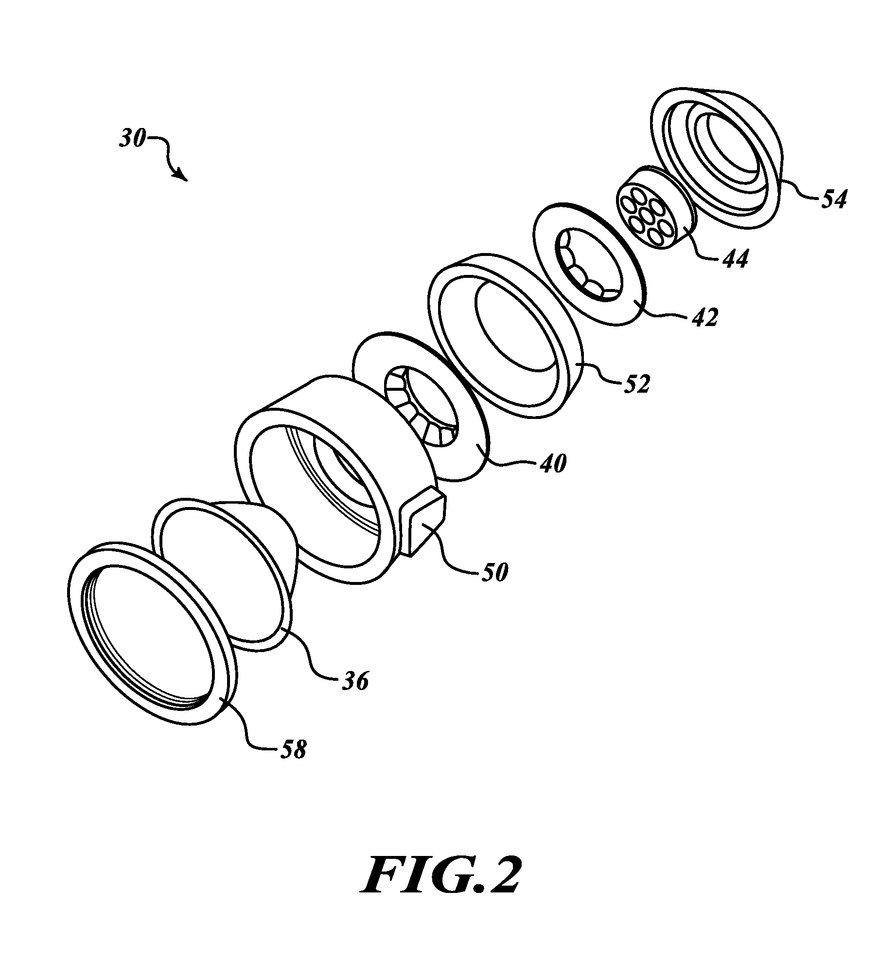
[0013]FIG. 2 illustrates an exploded view of the light assembly 30. In this embodiment, the light assembly 30 includes three LED layers 40, 42, 44. The first and second LED layers 40, 42 are ring-shaped and the third layer LED layer 44 is si...


PUM


Abstract

One or more layers of LEDs shine light into an array of elliptical reflectors. Each elliptical reflector has an LED at one focal point and shares the second focal point with a larger parabolic reflector that collimates the light. A hole in the center of the parabolic reflector receives additional LEDs, with or without collimation optics.

Description

BACKGROUND OF THE INVENTION[0001]Light Emitting Diode (LED) technology offers advantages in efficiency and life over traditional incandescent or halogen lights. Typical LED lamp design approaches use a planar array of LEDs with one or more collimating optics to achieve the desired photometric distribution. Many LED lamps used as alternatives to Parabolic Aluminized Reflector (PAR) lamps cannot match the photometric performance for a given frontal area compared to the conventional lamps they would replace, particularly for applications that require very high peak intensities such as a PAR64 aircraft landing light or an entertainment stage light.SUMMARY OF THE INVENTION[0002]Instead of a simple forward facing planar array that might typically be used for a PAR lamp replacement, the present invention uses depth of the package to increase the total peak intensity. One or more layers of LEDs shine into an array of elliptical reflectors. Each elliptical reflector has an LED at one focal p...

Claims


Application Information

Patent Timeline
Patent Type & Authority Patents(United States)
IPC IPC(8): F21V13/02
CPCF21V7/0025F21V7/0008F21V7/0083F21Y2113/005F21V7/08F21W2131/406F21Y2101/02F21V7/06F21Y2115/10F21Y2113/13
Inventor SINGER, JEFFREY M.BARNETT, DAVIDMANGUM, SCOTT R.
Owner HONEYWELL INT INC
Why Eureka
Try Eureka