Enhanced battery storage and recovery energy systems

a battery storage and recovery energy technology, applied in the field of energy storage systems, can solve the problems of reducing system efficiency, inefficient current system for balancing voltage, and inefficiency that typically only gets worse, so as to achieve the effect of minimizing the voltage imbalan

Active Publication Date: 2013-03-26
NEWLIGHT CAPITAL LLC
View PDF47 Cites 118 Cited by
  • Summary
  • Abstract
  • Description
  • Claims
  • Application Information

AI Technical Summary

Benefits of technology

[0007]In one of many embodiments of the present invention, apparatuses include an energy storage system. The energy storage system comprises two or more batteries connected in series. The two or more batteries form two sets of batteries wherein each set of batteries can comprise one or more batteries. The energy storage system comprises a regulator circuit configured to balance voltages across the two sets of the batteries. The regulator circuit may comprise at least one switchable connection and at least one energy storage unit. The at least one switchable connection may connect the at least one energy storage unit to the two sets of batteries. The energy storage system comprises a controller connected to the regulator circuit. The controller is configured to monitor voltages across the two sets of the batteries. The controller is configured to identify voltage imbalances between the two sets of the batteries. The controller is configured to adjust the regulator circuit so that the voltage imbalances between the two sets of the batteries are minimized.

Problems solved by technology

Current systems for balancing voltages are inefficient and these inefficiencies typically only get worse as the number of batteries increases (larger energy storage systems).
Voltage imbalances between batteries decrease system efficiency and limit the number of batteries that can be connected in series.
Importantly, voltage imbalances may become harder to mitigate as the number of batteries connected in series increases.
The same problem threatens future power grids since they too will rely largely on wind and solar power.

Method used


Image

  • Enhanced battery storage and recovery energy systems
  • Enhanced battery storage and recovery energy systems
  • Enhanced battery storage and recovery energy systems

Examples


third embodiment

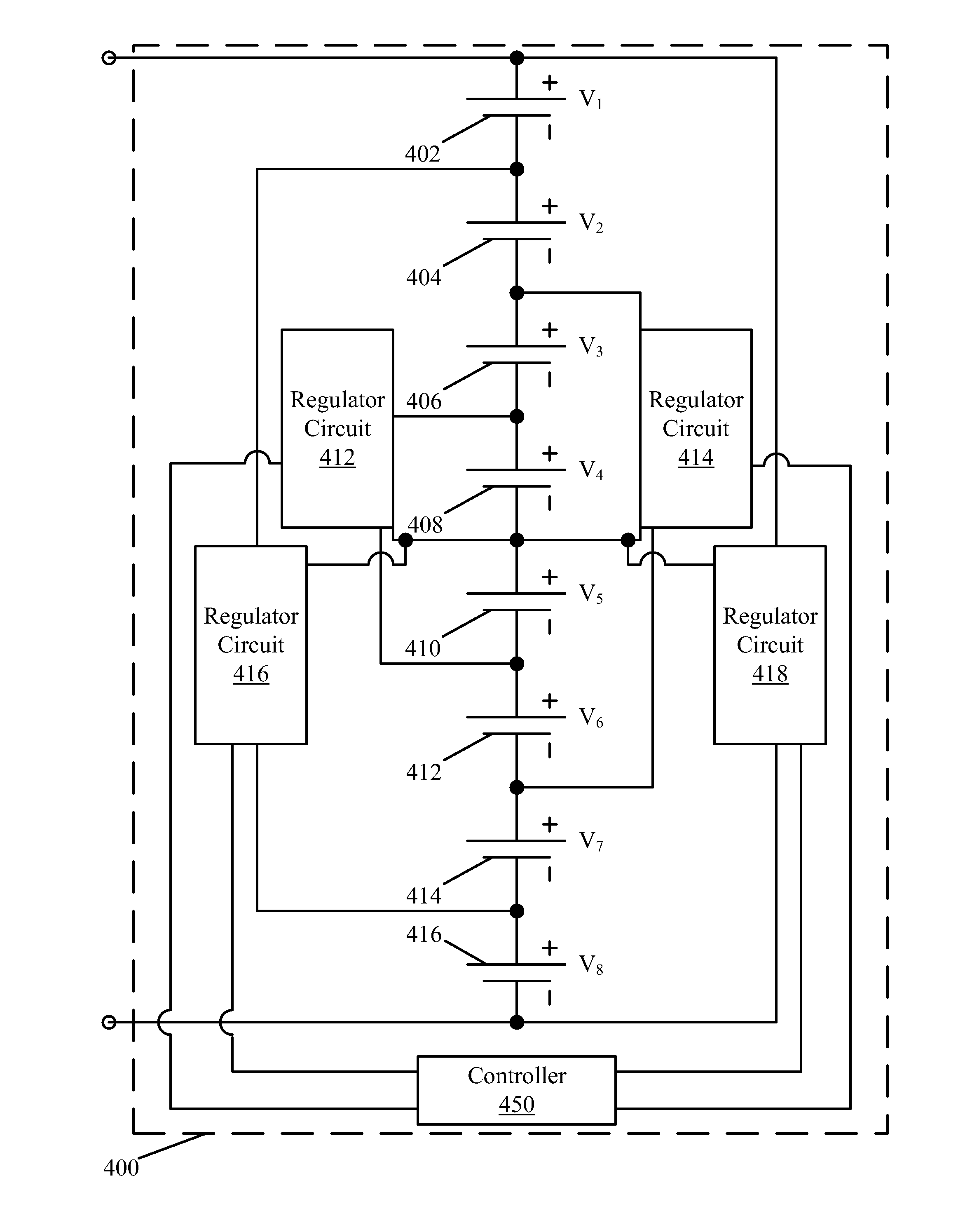
[0033]In an embodiment, a set of batteries can include one battery, or two or more batteries. Thus, for example, when reference is made to balancing two sets of batteries, where a first set comprises one battery, A, and the second set comprises three batteries, B, C, and D, what is meant is that the voltage across battery A is being balanced relative to the average voltage across batteries B, C, and D (e.g., VA=(VB+VC+VD) / 3). As a further example of this third embodiment, when reference is made to balancing two sets of batteries, where a first set comprises two batteries A and B, and the second set comprises three batteries C, D, and E, what is meant is that the average voltage across batteries A and B is being balanced relative to the average voltage across batteries C, D, and E (e.g., (VA+VB) / 2=(Vc+VD+VE) / 3). The details of such balancing are discussed later in this disclosure.

[0034]In an embodiment, sets of batteries can overlap. For instance, given three batteries, A, B, and C, ...

first embodiment

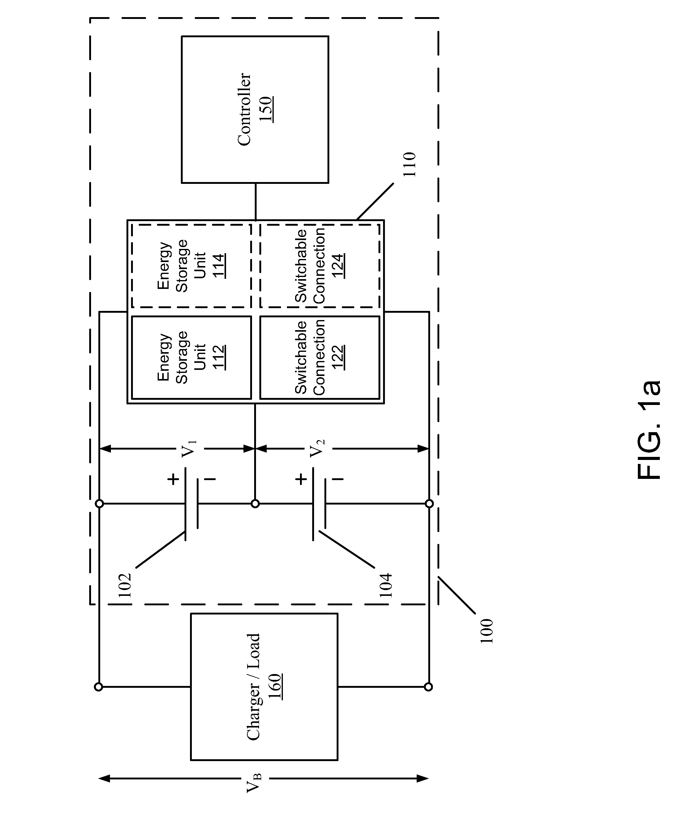
[0081]FIG. 6 illustrates a method of operating the herein disclosed energy storage system. The method 600 may include a charging or discharging a battery operation 602. The battery being charged or discharged can comprise two or more batteries connected in series.

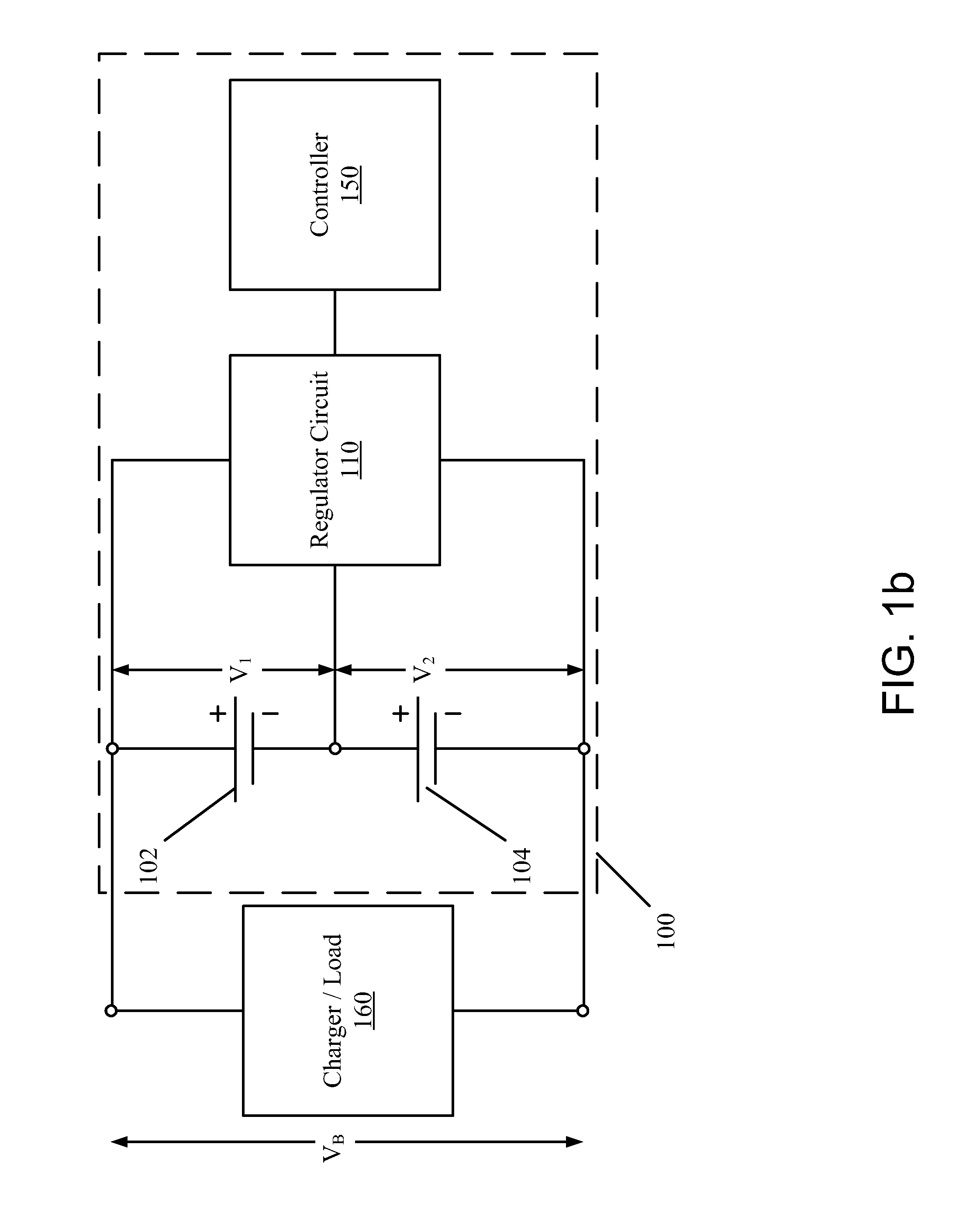
[0082]While the battery is being charged or discharged, a first voltage V1 across a first set of batteries and a second voltage V2 across a second set of batteries can be monitored. As such, the method 600 may include a monitor first voltage V1 operation 604. The method 600 may also include a monitor second voltage V2 operation 606.

[0083]Once the first and second voltages V1, V2 have been monitored (observed or measured), the difference (|V1-V2|) between the first and second voltages V1, V2 can be determined. This difference can be compared to the voltage imbalance threshold VT to determine if the voltage difference exceeds the threshold (|V1-V2|>VT) in a difference determination 608. If the difference is equal to or less t...

second embodiment

[0085]FIG. 7 illustrates a method of operating the herein disclosed energy storage system. The method 700 is similar to the method 600 with two differences. First, since the method 700 assumes that the regulator circuits comprise switches, the method 700 also accounts for duty cycle instructions. Thus, in the method 700, instructions may be initially provided to the switches in the one or more regulator circuits to operate at the default duty cycle (instruct operation 703). For energy storage systems where the number of batteries in each set of batteries is equal, the default duty cycle may be 50%. For energy storage systems where the numbers of batteries in each set of batteries is not equal, the default duty cycle may be greater or less than 50%. The exact default duty cycle may depend on the configuration of regulator circuits.

[0086]Second, if the difference in voltage determination 708 determines that the magnitude of the difference between the voltages |V1-V2| across two sets o...


PUM


Abstract

Systems and methods are herein disclosed for efficiently and cost-effectively balancing the voltages across batteries and / or cells in an energy storage system. A controller monitors the battery voltages and instructs regulator circuits to balance voltages between any batteries or sets of batteries having imbalanced voltages. Regulator circuits implementing a modified Ćuk converter can be utilized. Regulator circuits can have two capacitive circuits, one inductive circuit, and two switches. Two capacitors, an inductor, and two field effect transistors can be used in each regulator circuit.

Description

CROSS-REFERENCE TO RELATED APPLICATIONS[0001]The present application claims the benefit of Provisional U.S. Patent Application Ser. No. 61 / 269,652, filed Jun. 25, 2009 and entitled “Enhanced Battery Storage and Recovery Energy Systems,” the disclosure of which is hereby incorporated by reference.FIELD OF THE TECHNOLOGY[0002]At least some embodiments of the disclosure relate to energy storage systems in general, and more particularly but not limited to, enhancing the efficiency and number of batteries in a rechargeable energy storage system.BACKGROUND[0003]Rechargeable energy storage systems having a large number of batteries that can charge and discharge with great efficiency may become increasingly important in the coming years. For instance electric and hybrid cars may benefit from larger energy storage systems and efficient charging and discharging. To supplement wind and solar power generation when there are lulls in the wind or diminished sunlight, large and efficient energy st...

Claims


Application Information

Patent Timeline
Patent Type & Authority Patents(United States)
IPC IPC(8): H02J7/00
CPCH02J7/0016Y02T10/7055Y02T10/70
Inventor KIKINIS, DANAVRUTSKY, MORDECHAY
Owner NEWLIGHT CAPITAL LLC
Why Eureka
Try Eureka