Light amount adjustment apparatus having plurality of plate-like light-shielding blade members and method of manufacturing the light-shielding blade members

a technology of light-shielding blades and adjustment apparatuses, which is applied in the direction of manufacturing tools, instruments, other domestic objects, etc., can solve the problems of flare and ghosts, degradation of image quality such as ghosts, and difficulty in determining injection molding conditions, so as to prevent degradation of image quality and reduce undesired reflection

Inactive Publication Date: 2013-03-26
CANON KK
View PDF10 Cites 2 Cited by
  • Summary
  • Abstract
  • Description
  • Claims
  • Application Information

AI Technical Summary

Benefits of technology

[0010]The present invention provides a light amount adjustment apparatus having light-shielding blade members that can be so manufactured by simple machining as to reduce undesired reflection on end faces of the light-shielding blade members which are parallel with an optical axis and prevent degradation in image quality such as flare and ghosts, and a method of manufacturing the light-shielding blade members.
[0015]According to the present invention, there can be provided a light amount adjustment apparatus having light-shielding blade members that can be so manufactured by simple machining as to reduce undesired reflection on end faces of the light-shielding blade members which are parallel with the optical axis and prevent degradation in image quality such as flare and ghosts, and a method of manufacturing the light-shielding blade members.

Problems solved by technology

It is known that, like other members in an image pickup lens, when the light-shielding blade members cause undesired internal reflection, this results in degradation in image quality such as flare and ghosts.
Also, it is known that in a diaphragm unit having light-shielding blade members, degradation in image quality such as ghosts occurs due to reflection on end faces of the light-shielding blade members which form an aperture and are parallel with an optical axis.
For this reason, injection molding performed so as to make end faces of light-shielding blade members thin-walled is accompanied with a difficulty in determining injection molding conditions.
For this reason, injection molding performed to form end faces of light-shielding blade members in a stepwise fine pattern comprised of a plurality of steps or a steplessly curved fine pattern by injection molding is also accompanied with a difficulty in determining injection molding conditions.

Method used


Image

  • Light amount adjustment apparatus having plurality of plate-like light-shielding blade members and method of manufacturing the light-shielding blade members
  • Light amount adjustment apparatus having plurality of plate-like light-shielding blade members and method of manufacturing the light-shielding blade members
  • Light amount adjustment apparatus having plurality of plate-like light-shielding blade members and method of manufacturing the light-shielding blade members

Examples


first embodiment

[0025]the present invention will now be described with reference to FIGS. 1 to 4B.

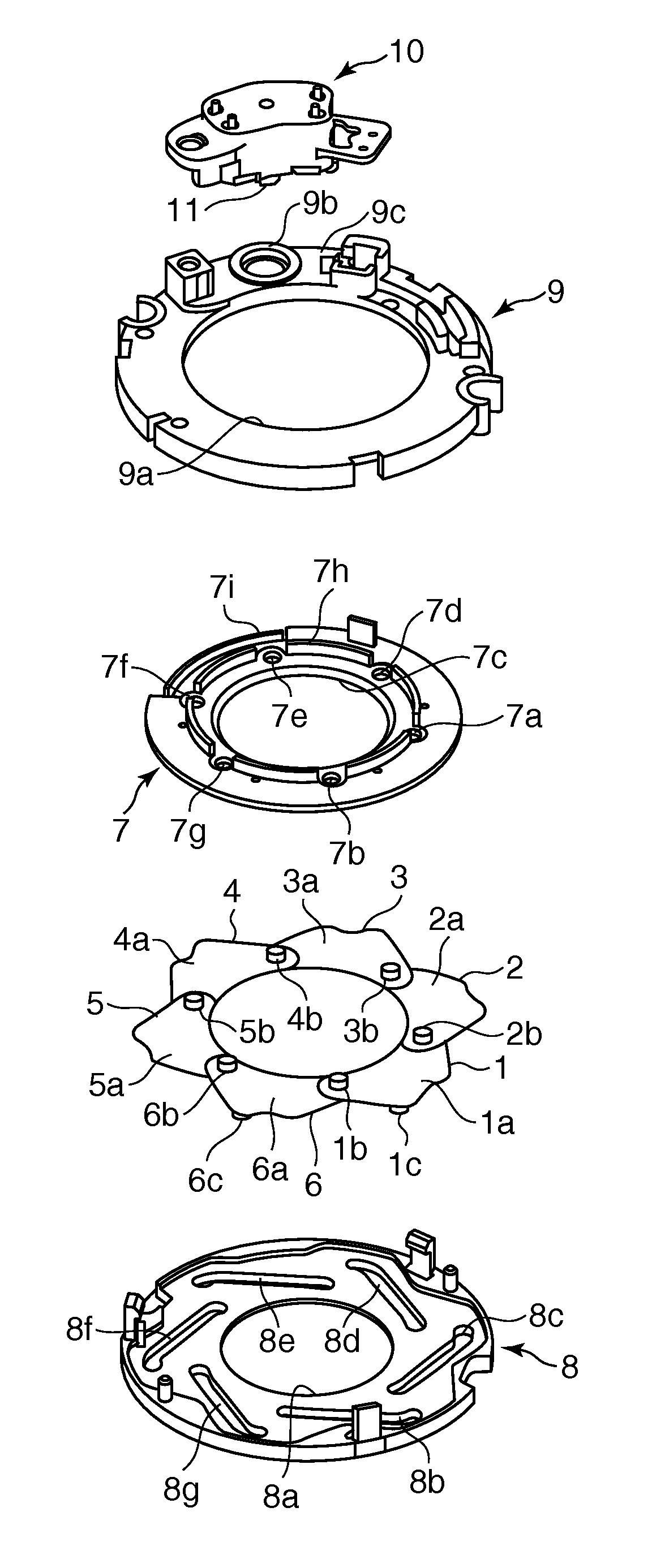
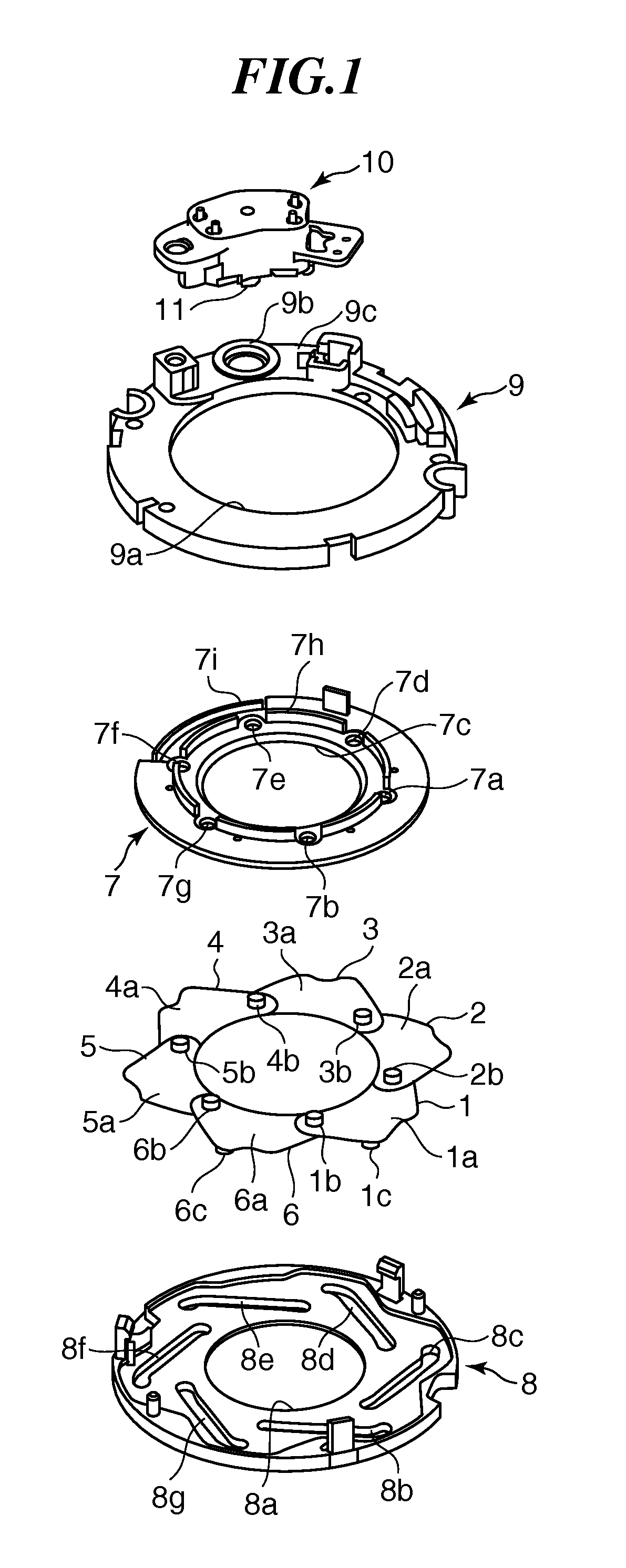
[0026]FIG. 1 is an exploded perspective view schematically showing essential constituent members of a light amount adjustment apparatus according to the first embodiment.

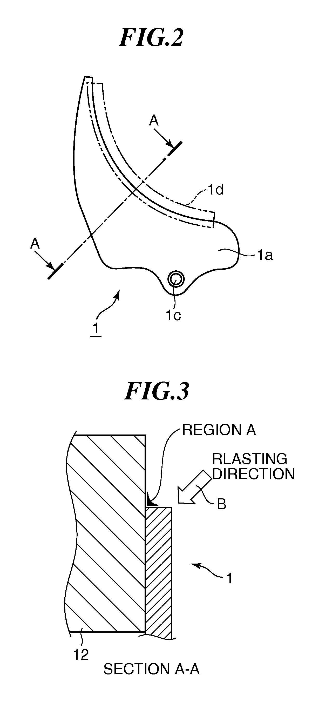
[0027]FIG. 2 is a plan view showing a light-shielding blade member for use in the light amount adjustment apparatus according to the first embodiment.

[0028]FIG. 3 is a view showing the light-shielding blade member cut along line A-A of FIG. 2 so as to explain a method of performing blasting on an end portion of the light-shielding blade member for use in the light amount adjustment apparatus according to the first embodiment.

[0029]FIG. 4A is an enlarged cross-sectional view showing the end portion of the light-shielding blade member according to the first embodiment cut along line A-A of FIG. 2 in a state before blasting as post-processing, and FIG. 4B is an enlarged cross-sectional view showing the end portion of the light-shielding b...

second embodiment

[0055]Next, the present invention will now be described with reference to FIGS. 5 to 8B.

[0056]FIG. 5 is an exploded perspective view schematically showing essential constituent members of a light amount adjustment apparatus according to the second embodiment.

[0057]FIG. 6 is a plan view showing a light-shielding blade member for use in the light amount adjustment apparatus according to the second embodiment.

[0058]FIG. 7 is a view showing the light-shielding blade member cut along line A-A of FIG. 6 so as to explain a method of performing blasting on an end portion of the light-shielding blade member for use in the light amount adjustment apparatus according to the second embodiment.

[0059]FIG. 8A is an enlarged cross-sectional view showing the end portion of the light-shielding blade member according to the second embodiment cut along line A-A of FIG. 6 in a state before blasting as post-processing, and FIG. 8B is an enlarged cross-sectional view showing the end portion of the light-s...


PUM

PropertyMeasurementUnit
timeaaaaaaaaaa
aperture diameteraaaaaaaaaa
diameteraaaaaaaaaa

Abstract

A light amount adjustment apparatus having a plurality of light-shielding blade members that can be so manufactured by simple machining as to reduce undesired reflection on end faces of the light-shielding blade members which are parallel with the optical axis and prevent degradation in image quality such as flare and ghosts. A driving force of a stepping motor is transmitted to the light-shielding blade members so that an aperture diameter can be changed. The light-shielding blade members are formed by injection molding of a light-shielding resin material. By performing blasting on an end face of each light-shielding blade member in a part that forms the aperture diameter, an aperture end face whose surface is roughened while substantially maintaining outside dimensions of the light-shielding blade member is formed, and an oblique portion tilted relative to the aperture end face is formed.

Description

BACKGROUND OF THE INVENTION[0001]1. Field of the Invention[0002]The present invention relates to a light amount adjustment apparatus for use in an image pickup apparatus, and in particular to a light amount adjustment apparatus having a plurality of plate-like light-shielding blade members and a method of manufacturing the light-shielding blade members.[0003]2. Description of the Related Art[0004]Generally, there are image pickup apparatuses such as digital cameras which use a diaphragm unit having light-shielding blade members mounted thereon. It is known that, like other members in an image pickup lens, when the light-shielding blade members cause undesired internal reflection, this results in degradation in image quality such as flare and ghosts. For this reason, surfaces of the light-shielding blade members are coated with a coating for light absorption so as to prevent degradation in image quality.[0005]Also, it is known that in a diaphragm unit having light-shielding blade mem...

Claims


Application Information

Patent Timeline
Patent Type & Authority Patents(United States)
IPC IPC(8): G02B26/02
CPCG02B5/005G02B27/0018G02B26/02
Inventor SAITO, JUNICHI
Owner CANON KK
Why Eureka
Try Eureka