
Apparatus and method for concentrating electromagnetic energy on a remotely-located object

a technology of electromagnetic energy and apparatus, applied in the direction of electrical apparatus, antennas, etc., can solve the problems of unsatisfactory and problematic intensely painful burning sensation, etc., and achieve the effect of reducing undesired reflection

Inactive Publication Date: 2012-05-31
DROSERA
View PDF6 Cites 5 Cited by
  • Summary
  • Abstract
  • Description
  • Claims
  • Application Information

AI Technical Summary

Benefits of technology

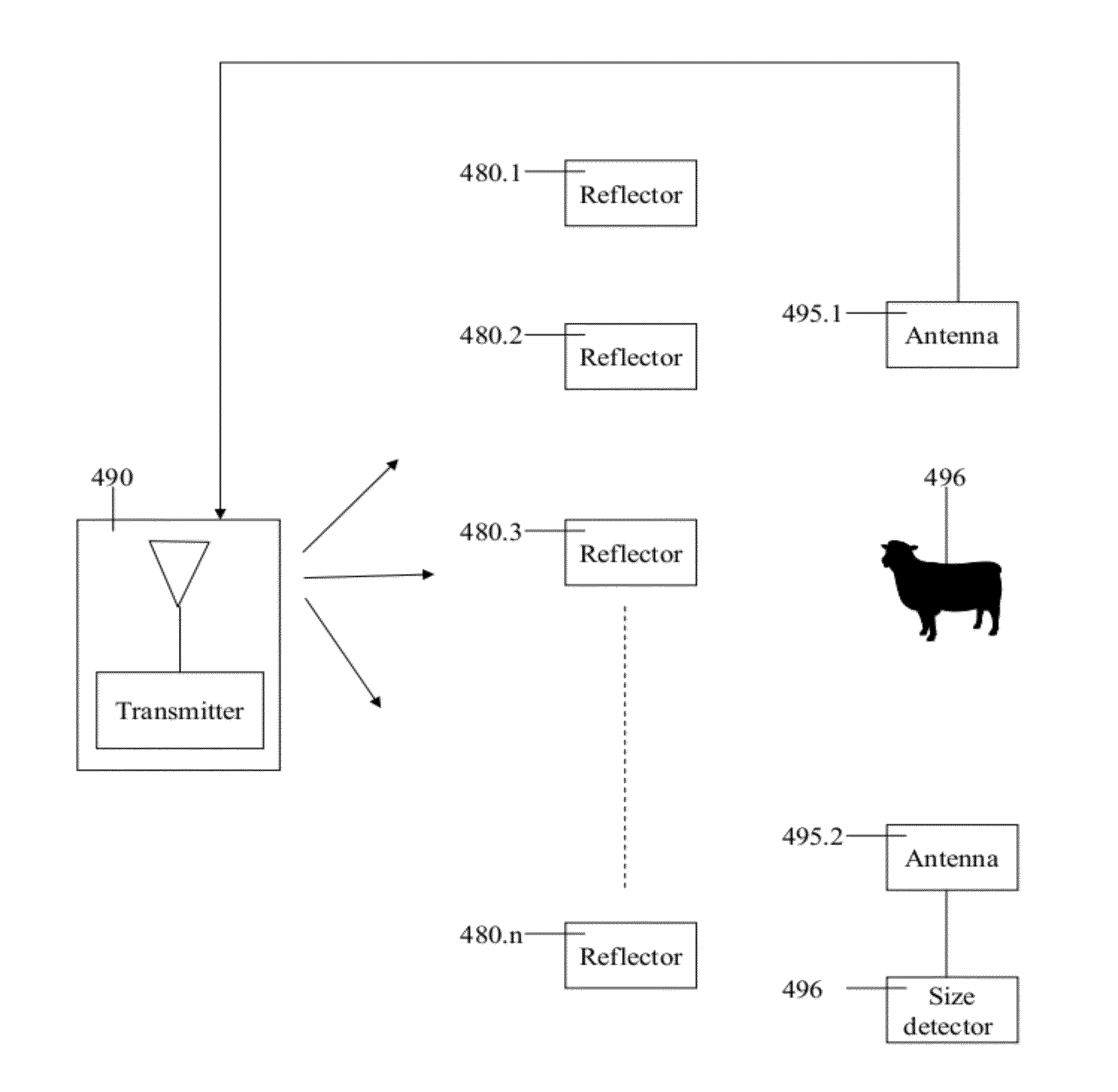
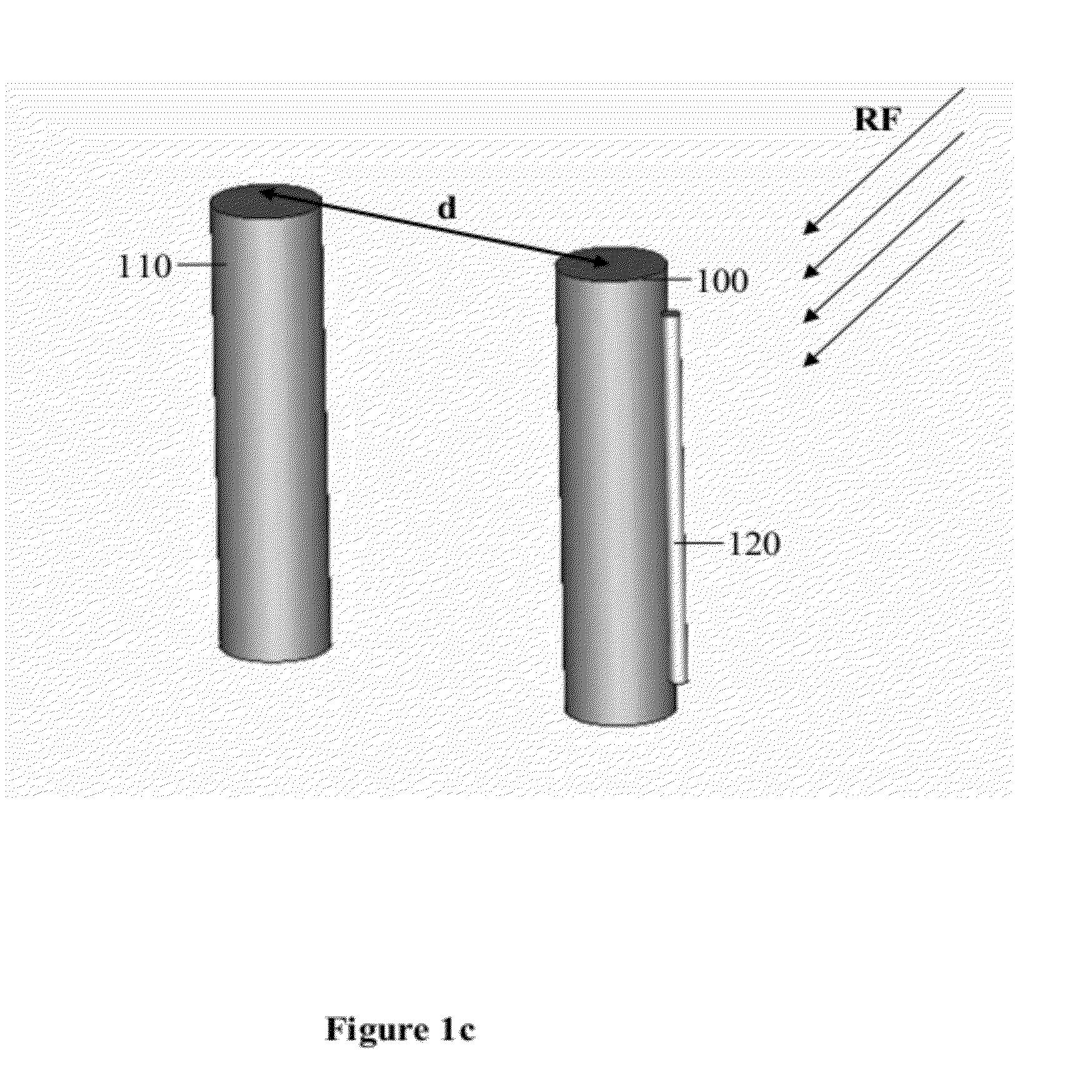
"The patent describes a method for concentrating RF radiation on an object located in proximity to a reflector. The method involves transmitting RF radiation towards the reflector and receiving the reflected RF radiation. The reflected RF radiation is then utilized as a passive source to deliver RF radiation to the absorbing object. The energy delivery is performed by transmitting RF radiation onto the reflector, which then couples with the electromagnetic field as an antenna. The amount of energy delivered to the object is significantly greater than the energy delivered to objects at a distance from the reflector. The method can be used for various applications such as security, heating, and controlling the environment. The resonance profile of the reflector is determined, and a transmission profile is transmitted that matches the resonance profile. The transmission power can be adjusted to control the level of radiation and can cause pain or discomfort to the object. The method can be used in a wide range of RF frequency bands."

Problems solved by technology

The power that is scattered by the RFID and its influence on nearby objects is a side effect which at times is undesired and problematic.
The waves excite water molecules in the skin, causing an intensely painful burning sensation.

Method used


Image

  • Apparatus and method for concentrating electromagnetic energy on a remotely-located object
  • Apparatus and method for concentrating electromagnetic energy on a remotely-located object
  • Apparatus and method for concentrating electromagnetic energy on a remotely-located object

Examples


first embodiment

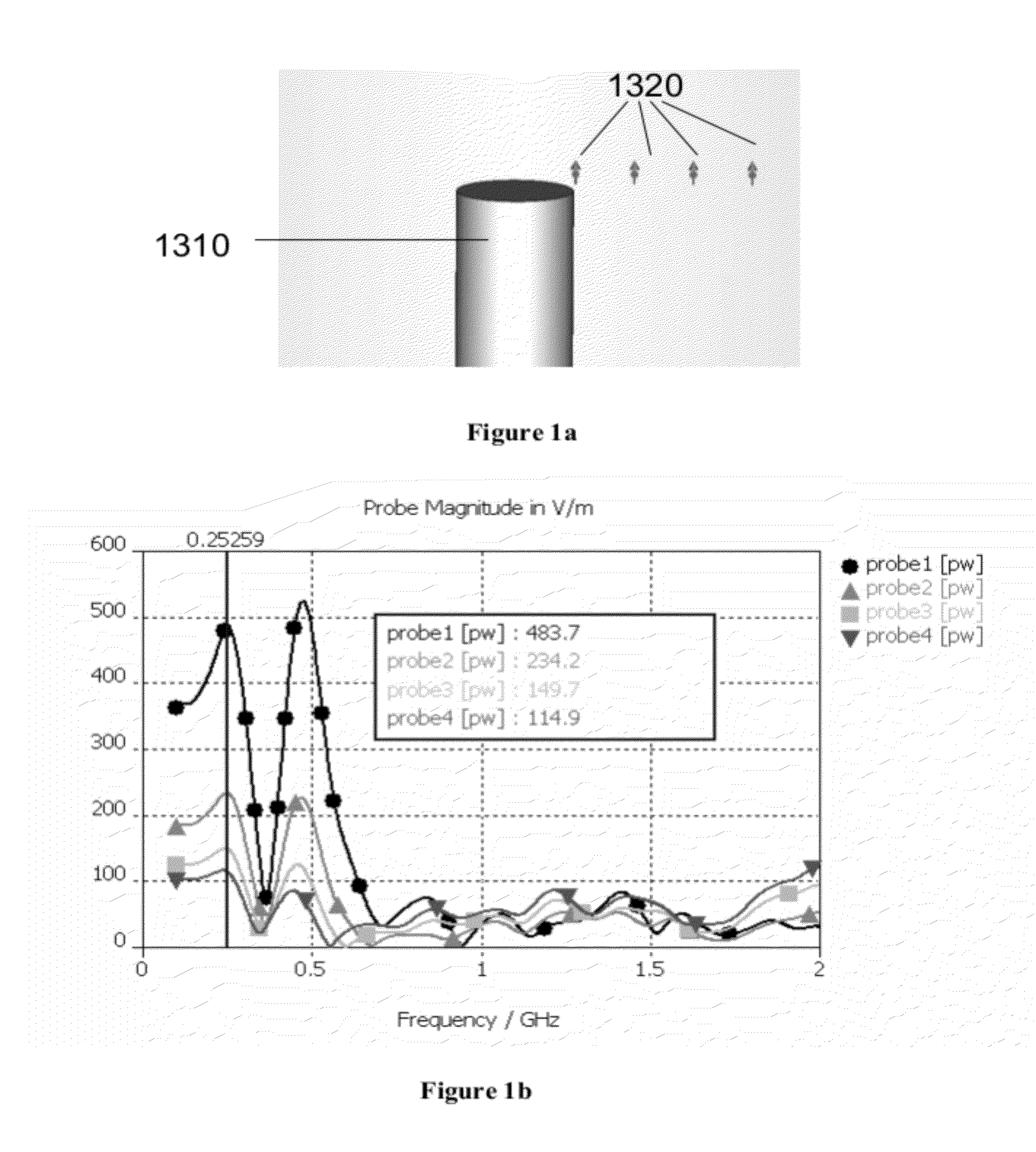
[0159]In a first embodiment, the transmission frequency (or frequencies) is defined within a frequency range of 20 MHz to 2 GHz, for irradiating elongated reflectors ranging in size between 8-750 cm. The frequency range of 20 MHz to 2 GHz is particularly suitable for targeting reflectors comprising weapons, such as guns or rifles or portions thereof (e.g. sights in sniper rifles). Sub-ranges may be used for more directed security embodiments. In an alternate embodiment, a frequency range of 188 MHz to 500 MHz is selected for targeting conventional guns ranging in size between 30 to 80 cm. In another embodiment, a frequency range of 100 MHz-188 MHz is selected for targeting longer guns (e.g. 80-150 cm). In yet another embodiment, a range of 600 MHz to 1.5 GHz is selected for targeting a portion of a gun (e.g. a sight piece of 10-25 cm).

second embodiment

[0160]In a second embodiment, the transmission frequency (or frequencies) is defined for a frequency range above 3 GHz. This range may be particularly suitable for the crowd control embodiment discussed herein, in which the reflectors may be small personal objects such as keys, watches, and jewelry.

[0161]In a further preferred embodiment, the transmitted RF radiation may be emitted in a frequency or band of frequencies close to or surrounding a known effective frequency range (e.g. + / −25% or + / −30% or less of a resonant peak frequency), such that at least a portion of the RF radiation produces a desired effect. Such a frequency or frequency band may be also derived from advance experimentation, providing an effective range to cover many deviations in position and surroundings. Although the present embodiment may be less energy efficient or less effective due to the lower levels of RF radiation which are reflected, it enables obtaining the desired effect even when the optimal transmi...


PUM


Abstract

A method for transmitting radio frequency (RF) radiation to an object located in proximity to a reflector includes the steps of: selecting a target reflector and a level of power for conveying to the target reflector by reradiation from the target reflector, determining a resonance profile of the target reflector, the resonance profile including at least one resonant frequency of the target reflector, selecting a transmission profile matching the resonance profile, the transmission profile comprising the at least one resonant frequency, and transmitting RF radiation in accordance with the transmission profile towards the target reflector.

Description

RELATED APPLICATION[0001]This application is a continuation of U.S. patent application Ser. No. 12 / 217,167 filed on Jul. 2, 2008, which claims the benefit of priority from Israel Patent Application No. 184672 filed on Jul. 17, 2007. The contents of all of the above applications are incorporated by reference as if fully set forth herein.FIELD AND BACKGROUND OF THE INVENTION[0002]The present invention relates to reflecting electro-magnetic energy from a passive source onto a proximate object, for example in order to reflect electro-magnetic energy from a weapon into a person in proximity to the weapon.[0003]A passive radiator (also named a passive director or reflector) is a radio-frequency (RF) radiation element which does not have any wired input. Instead, it is coupled to radio waves radiated from another active antenna element, and reradiates (i.e. reflects) the RF energy. The reradiation pattern (also named herein the resonance profile) is determined by factors such as the dimens...

Claims


Application Information

Patent Timeline
Patent Type & Authority Applications(United States)
IPC IPC(8): H01Q15/00
CPCH01Q19/18
Inventor BEN-SHMUEL, ERAN
Owner DROSERA
Learn More