Running tool

a running tool and tool body technology, applied in the field of running tools, can solve the problems of running tool becoming stuck in the hanger, incorrect positioning of sealing/packing, and inability to properly set the sealing seal

Active Publication Date: 2013-04-02
VETCO GRAY
View PDF14 Cites 8 Cited by
  • Summary
  • Abstract
  • Description
  • Claims
  • Application Information

AI Technical Summary

Benefits of technology

[0005]In an embodiment of the present technique, a running tool for setting and testing a packoff seal of a well pipe hanger has an elongated stem having an axial passage. A body substantially surrounds and is connected to the stem. A cam is positioned between and connected to the body and the stem such that rotation of the stem causes the cam to translate axially relative to the body. A cam tail is connected to the cam such that it translates in unison with the cam. A stem engagement element is carried by the body and is adapted to be engaged with the stem at a run-in position and a landing position to restrict axial translation of the stem elative to the body. The cam tail acts to maintain the engagement of the engagement element with the stem in the run-in position, and to release the engagement element from engagement with the stem in a delivery position. A piston is connected to the stem such that the piston and the stem rotate in unison. The piston substantially surrounds portions of the stem and the body.
[0006]In an embodiment of the present technique, a running tool for setting and testing an annular seal having an energizing ring in a subsea well has a member adapted to position the annular seal within the subsea well. A piston is adapted to drive the energizing ring to set the annular seal in the subsea well. An engagement system is adapted to provide an indication as to whether the member has delivered the annular seal to a correct location in the subsea well, thereby ensuring that the annular seal is set in a proper location within the subsea well.

Problems solved by technology

However, if the stem does not travel a sufficient distance to properly land the packoff seal, the seal may be set in an incorrect position.
The consequence of an improperly set packoff seal may result in a running tool becoming stuck in a hanger, or alternatively, may require several trips to retrieve the seal, clean the area, and set another seal.
Furthermore, if the running tool piston does not stroke the packoff seal sufficiently once landed, the packoff seal will not properly set.

Method used


Image

  • Running tool
  • Running tool
  • Running tool

Examples


Embodiment Construction

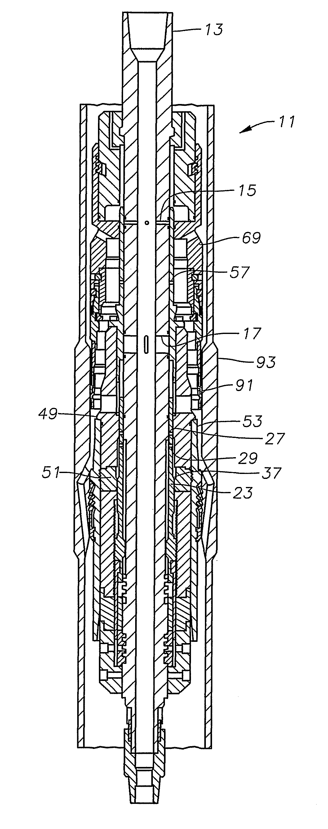
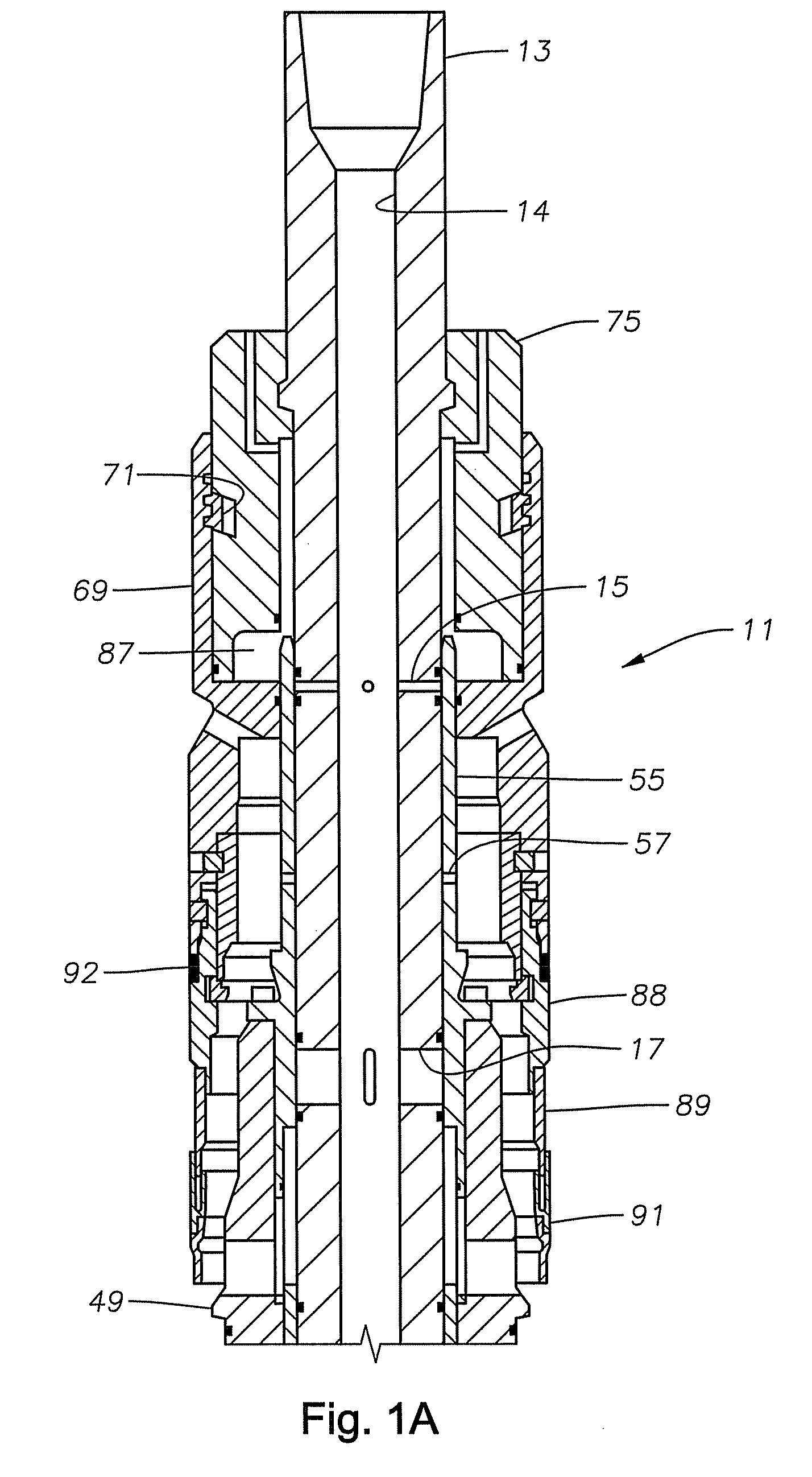
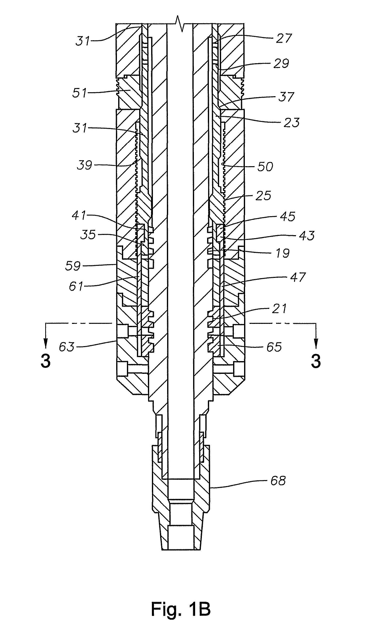
[0025]Referring to FIG. 1, there is generally shown an embodiment of a running tool 11 that is used to set and internally test a casing hanger packoff. In this embodiment, the running tool 11 is a two-port casing hanger running tool. The running tool 11 is comprised of a stem 13. In this embodiment, the stem 13 is a tubular member with an axial passage 14 extending therethrough. The stem 13 connects on its upper end to a sting of drill pipe (not shown). The stem 13 has an upper stem port 15 and a lower stem port 17 positioned in and extending radially therethrough that allow fluid communication between the exterior of the running tool 11 and the axial passage 14 of the stem 13. The stem 13 has an upper contoured surface 19 and a lower contoured surface 21 located in the outer diameter of the stem 13 a distance below the lower stem port 17. The upper contoured surface 19 is spaced apart from the lower contoured surface 21 a specified amount.

[0026]A cam 23 is a sleeve connected to and...


PUM


Abstract

An embodiment of a running tool for setting and testing a packoff seal of a well pipe hanger has an elongated stem having an axial passage, a body, a cam, a cam tail, a stem engagement element, and a piston. A method of setting and testing a packoff seal comprises rotating the stem relative to the body to a delivery position, thereby disengaging the engaging element from the stem. The stem moves axially downward relative to the body to land the packoff. The engagement element reengages the stem in a landing position. Fluid pressure is applied to the axial passage to set and seal the packoff, thereby moving the running tool to a set position.

Description

FIELD OF THE INVENTION[0001]This technique relates in general to tools for setting and testing well pipe hanger packoff seals in subsea wells, and in particular to a running tool with an internal test feature that prevents the setting of a packoff seal in an incorrect position.BACKGROUND OF THE INVENTION[0002]A subsea well of the type concerned herein will have a wellhead supported on the subsea floor. One or more strings of casing will be lowered into the wellhead from the surface, each supported on a casing hanger. The casing hanger is a tubular member that is secured to the threaded upper end of the string of casing. The casing hanger lands on a landing shoulder in the wellhead, or on a previously installed casing hanger having larger diameter casing. Cement is pumped down the string of casing to flow back up the annulus around the string of casing. Afterward, a packoff is positioned between the wellhead bore and an upper portion of the casing hanger. This seals the casing hanger...

Claims


Application Information

Patent Timeline
Patent Type & Authority Patents(United States)
IPC IPC(8): E21B33/04
CPCE21B33/04E21B2033/005E21B2200/01E21B23/00E21B33/043
Inventor EPPINGHAUS, GUILHERMEGETTE, NICHOLAS P.
Owner VETCO GRAY
Why Eureka
Try Eureka