Gas burner

a burner and gas technology, applied in the field of gas burners, can solve the problems of large space requirements and insufficient adaptability of most of these designs

Inactive Publication Date: 2013-04-02
AB ELECTROLUX
View PDF32 Cites 12 Cited by
  • Summary
  • Abstract
  • Description
  • Claims
  • Application Information

AI Technical Summary

Benefits of technology

[0014]The separate or discrete segments can include interlocking formations thereon so that adjacent burner segments can be assembled together. Alternatively or additionally, the separate or discrete segments are held together as an assembly by means of a interaction with a burner cap. Alternatively or additionally a circumferential fixing means assists in holding or holds said separate or discrete segments together as an assembly to form a distributor.
[0032]Each said injector can be shielded by a portion of a wall of said distributor means to prevent air passing in through said air entry port from disturbing the operation of said injector.
[0060]The separate or discrete segments can include interlocking formations thereon so that adjacent burner segments can be assembled together. Alternatively or additionally, the separate or discrete segments are held together as an assembly by means of a interaction with a burner cap. Alternatively or additionally a circumferential fixing means assists in holding or holds said separate or discrete segments together as an assembly to form a distributor.

Problems solved by technology

However, it is common to these constructions that they require a fairly large space below the hob surface to accommodate the injector.
Also, most of these designs are not sufficiently adaptable, for instance in cases where it is desired to use one and the same burner configuration as the basis for a burner that could heat up a larger area of a cooking utensil, such as an ordinary cooking pot or frying pan.

Method used


Image

  • Gas burner
  • Gas burner
  • Gas burner

Examples


Embodiment Construction

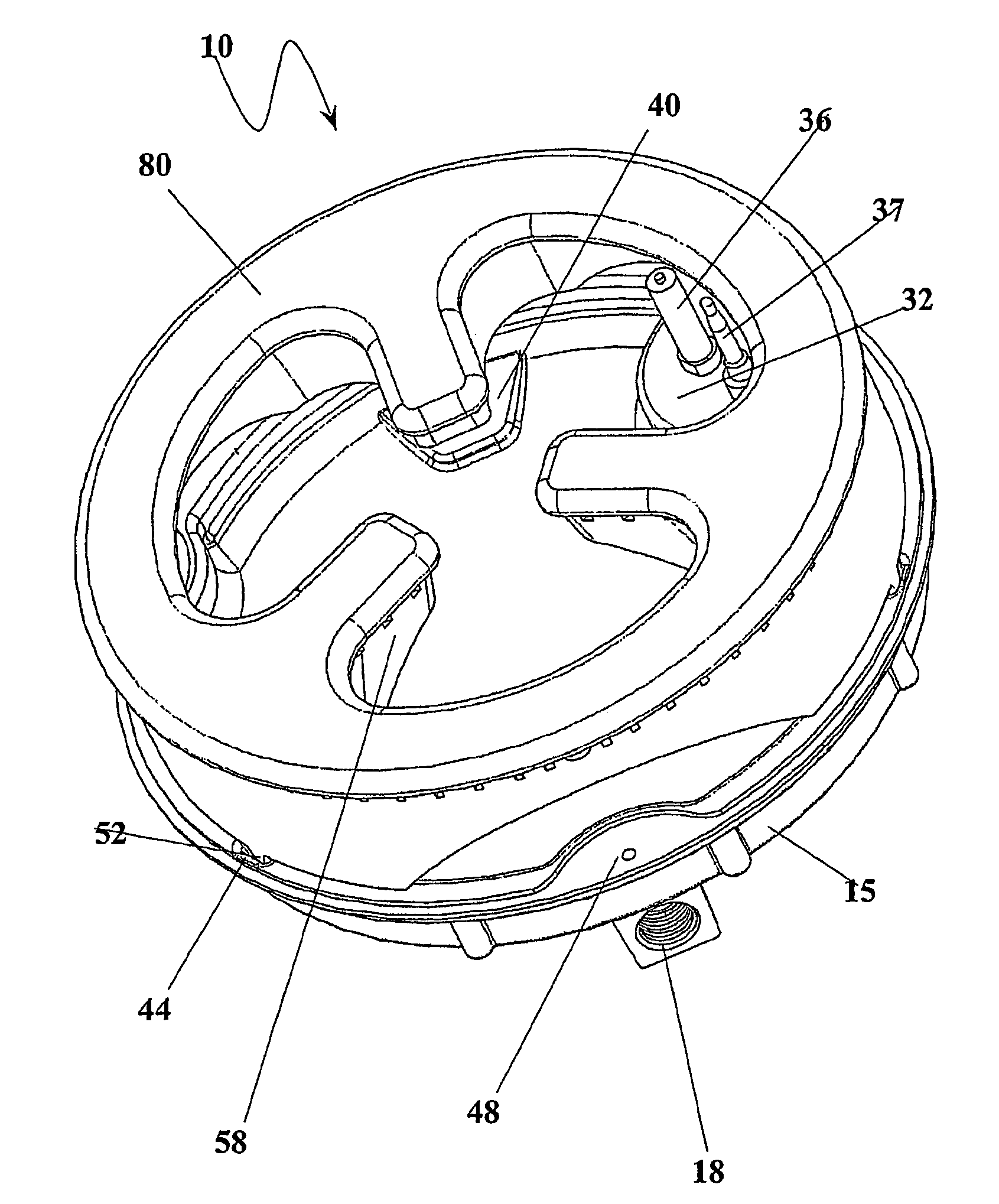
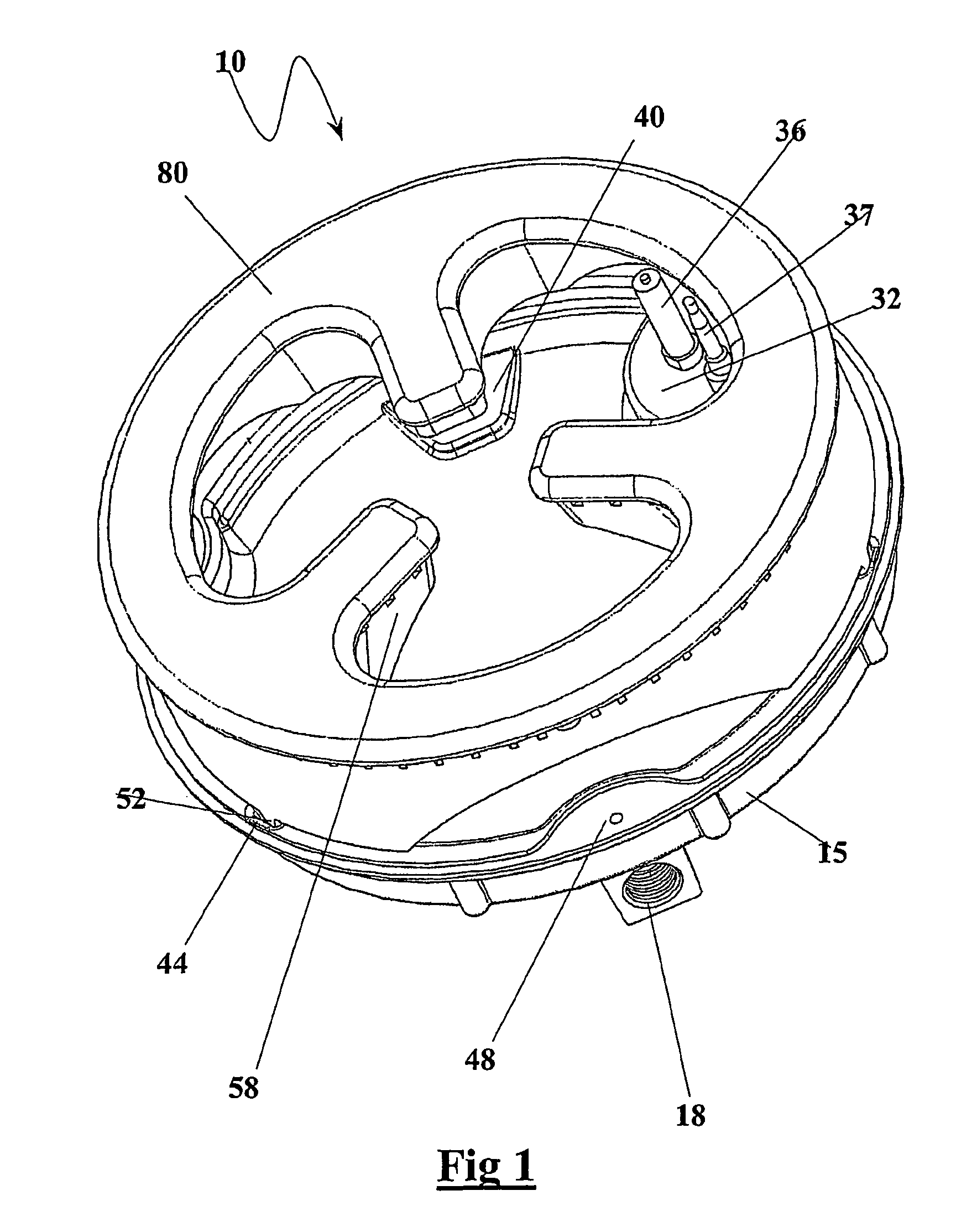
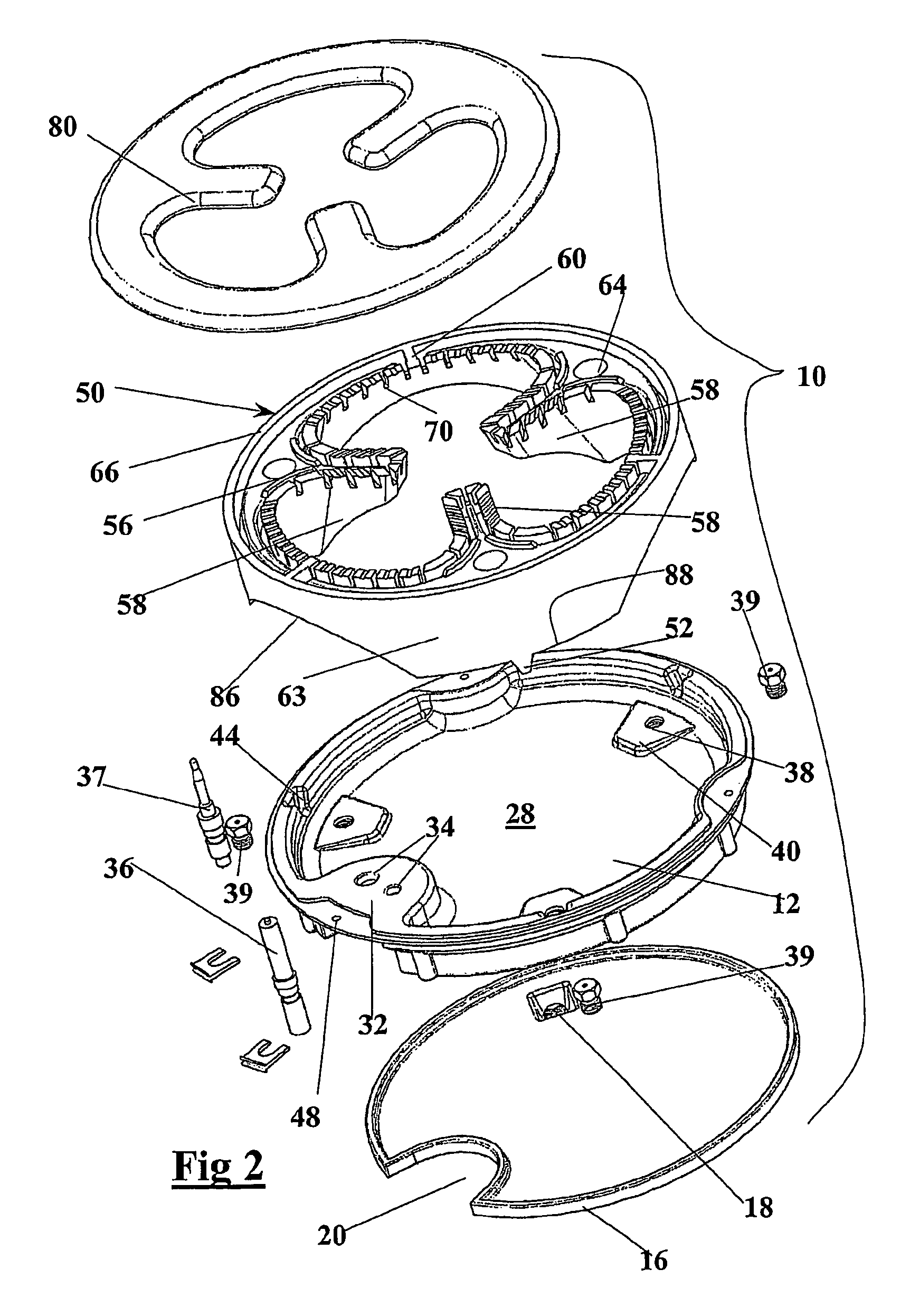
[0101]Illustrated in FIGS. 1 to 7 is a burner 10 which is an assembly of several components including a manifold 15 which forms the base of the burner 10. The manifold 15 is an assembly of a manifold top member 14 and a manifold bottom member 16. The manifold top member 14 has its upper surface generally concave and thereby forms a cup 12. The manifold bottom member 16 has a threaded female gas supply connection 18 and a cut out portion 20 which receives the downwardly projecting side wall of the boss 32 on the base of manifold top member 14 to fit therein. The purpose of the boss 32 will be discussed below.

[0102]The nature of the manifold top member 14 and manifold bottom member 16 is that they can be manufactured from relatively thin sections making them relatively simple to manufacture by any one of several methods such as injection moulding, casting or pressing.

[0103]The manifold bottom member 16 has four downwardly extending supports 24 which rest against the upper surface of a...


PUM


Abstract

The present invention provides a gas burner (10) including: a distributor means (50) having at least one distribution chamber to distribute an air gas mixture around said distributor (50), said burner (10) including a plurality of flame ports (70) through which said gas mixture can pass and be ignited; at least one injector (39) associated with said distributor (50), said at least one injector (39) being positioned to inject gas into said at least distribution chamber via a venture formed of a vertically directed passage and transition port (64) and at least one venturi extension extending away from said transition port (64). The present invention also provides manifold for a gas burner (10), said manifold having an upper wall (12) and a lower wall (16) held in spaced apart relationship by a peripheral wall to define a cavity there between, said manifold including means (38) to mount at least one injector (39) so as to deliver an air gas supply to a distribution means (50) and an inlet port (18) to allow connection to a supply of gas, which can pressurize said cavity, said upper (12) and said lower (16) wall being formed from relatively thin sections.

Description

FIELD OF THE INVENTION[0001]The present invention relates to gas burners for cooking stoves and in particular to a gas burner suitable for use with a wok.BACKGROUND OF THE INVENTION[0002]Wok burners are in the main single injector designs and aim at concentrating the heat at the centre of the burner, corresponding to the bottom of the wok. Such burners are known from documented prior art constructions, such as those found in DE3918715 and similar designs, such as U.S. Pat. No. 6,688,882 and U.S. Pat. No. 6,089,219, as well as JP10-185212 and JP10-160127. However, it is common to these constructions that they require a fairly large space below the hob surface to accommodate the injector. Also, most of these designs are not sufficiently adaptable, for instance in cases where it is desired to use one and the same burner configuration as the basis for a burner that could heat up a larger area of a cooking utensil, such as an ordinary cooking pot or frying pan. Even those documents among...

Claims


Application Information

Patent Timeline
Patent Type & Authority Patents(United States)
IPC IPC(8): F23D14/62F23D14/06F23D23/00
CPCF23D14/06F23D2900/14064F23D2900/14062F23D2900/14063
Inventor ROSSI, CARLO ANTONIOROSSI, MARCOMCINTYRE, STEVENBORG, KEITH JOSEPHBROCK-NANNESTAD, GEORGE
Owner AB ELECTROLUX
Why Eureka
Try Eureka